Measuring Instruments
Anyone who wants to work in the air conditioning and refrigeration field must become proficient with the common instruments used to measure electrical quantities. These instruments are the voltmeter, am- meter, and ohmmeter. In the air-conditioning and refrigeration field, the technician works almost exclusively with alternating current. For this reason, the meters covered in this unit are intended to be used in an alternating current system.
VOLTMETER
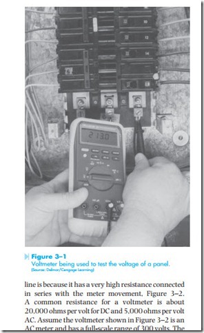
The voltmeter is designed to be connected directly across the source of power. Figure 3–1 shows a voltmeter being used to test the voltage of a panel box. Notice that the leads of the meter are connected directly across the source of voltage. The reason a voltmeter can be connected directly across the power
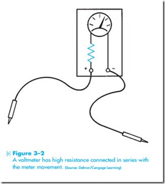
line is because it has a very high resistance connected in series with the meter movement, Figure 3–2. A common resistance for a voltmeter is about 20,000 ohms per volt for DC and 5,000 ohms per volt AC. Assume the voltmeter shown in Figure 3–2 is an AC meter and has a full-scale range of 300 volts. The resistor connected in series with the meter would, therefore, have a resistance of 1,500,000 ohms (300 volts X 5,000 ohms per volt = 1,500,000 ohms).
Most voltmeters are multiranged, which means that they are designed to use one meter movement to measure several ranges of voltage. For example, one meter may have a selector switch that permits full-scale ranges to be selected. These ranges may be 3 volts full-scale, 12 volts full-scale, 30 volts full-scale, 60 volts full-scale, 120 volts full- scale, 300 volts full-scale, and 600 volts full-scale.
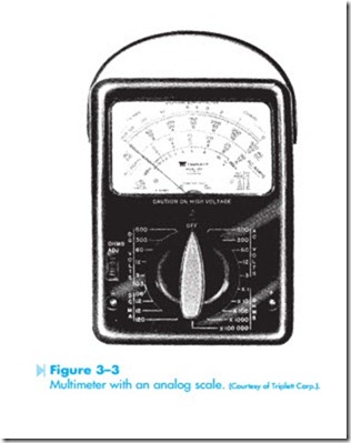
The reason for making a meter with this number of scales is to make the meter as versatile as possible. If it is necessary to check for a voltage of 480 volts, the meter can be set on the 600-volt range. If it becomes necessary to check a control voltage of 24 volts, however, it would be very difficult to do on the 600-volt range. If the meter is set on the 30-volt range, however, it becomes a simple matter to test for a voltage of 24 volts. The meter shown in Figure 3–3 has multirange selection for voltage.
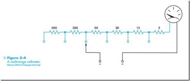
When the selector switch of this meter is turned, steps of resistance are inserted in the circuit to in- crease the range, or removed from the circuit to decrease the range, Figure 3–4. Notice that when the higher voltage settings are selected, more resistance is inserted in the circuit.
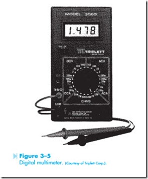
Another type of voltmeter that is gaining popularity is the digital meter. A digital meter dis- plays the voltage in digits instead of using a meter movement, Figure 3–5. Digital meters have several advantages over voltmeters that use a meter movement (commonly called analog meters). The greatest advantage is that the input impedance, or resistance, is higher. Analog meters commonly
have a resistance of about 5,000 ohms per volt. This means that on a 3-volt full-scale range, the meter movement has a resistance of 15,000 ohms connected in series with it (3 X 5,000 = 15,000). On the 600-volt full-scale range, the meter movement has a resistance of 3,000,000 ohms connected in series with it (600 X 5,000 = 3,000,000). Digital meters commonly have an input impedance of
10,000,000 ohms (10 megohms), regardless of the range they are set on. The advantage of this high input impedance is that it does not interfere with a low-power circuit. The advantage of this may not be too clear at first, because most technicians are used to working with circuits that have more than enough power to operate the meter. However, many of the newer controls are electronic; these circuits may be greatly altered if tested with a low impedance meter.
For example, assume an electronic control is operated on 5 volts, and has a total current capacity of 100 microamps (.000100 amps). Now assume that a 5,000-ohm-per-volt meter is set on the 12-volt scale and is to be used to check the control circuit. The voltmeter has a resistance of 5,000 X 12 = 60,000 ohms. If this meter is used to test the circuit, the meter will have a current draw of 83.3 microamps (5 volts/60,000 ohms = .0000833 amps). Because the control circuit only has a total current capacity of 100 microamps, the meter is using most of the current to operate. The circuit has been changed to such a degree that it can no longer operate.
If the digital meter is used to test this same circuit, it will have a current draw of 0.5 microamp (5 volts/10,000,000 = .00000005 amp). The circuit will be able to furnish the 0.5 microamp needed to operate the meter without a problem or altering the circuit.
Another advantage of the digital meter is that it is generally easier for an inexperienced person to learn to read. Analog meters can be used for about
99% of the measurements that must be taken, but it generally takes some time and practice to read them properly.
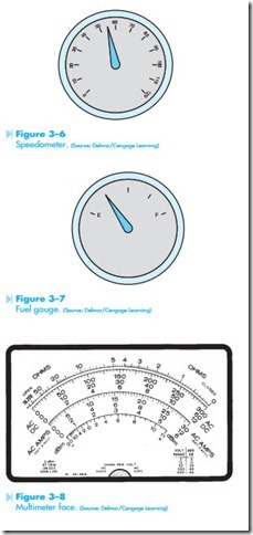
Learning to read the scale of a multimeter takes time and practice. Most people use meters every- day without thinking about it. A very common type of meter used daily by most people is shown in Figure 3–6. The meter illustrated is a speedometer similar to those seen in an automobile. This meter is designed to measure speed. It is calibrated in miles per hour (mph). The speedometer shown has a full-scale value of 80 mph. If the pointer is positioned as shown in Figure 3–6, most people would know instantly that the speed of the automobile is 55 mph.
Figure 3–7 illustrates another common meter used by most people. This meter is used to measure the amount of fuel in the tank of an automobile. Most people can glance at the pointer of the meter and know that the meter is indicating that there is one-quarter of a tank of fuel remaining. Now assume that the tank has a capacity of 20 gallons. The meter is now indicating that there are a total of 5 gallons of fuel remaining in the tank.
Learning to read the scale of a multimeter is similar to learning to read a speedometer or fuel
gauge. The meter scale shown in Figure 3–8 has several scales used to measure different values and quantities. The very top of the scale is used to measure resistance or ohms. Notice that the scale begins at the left-hand side with infinity, and zero can be found at the far right-hand side. Ohmmeters will be covered later in this unit. The second scale is labeled AC–DC and is used to measure volt- age. Notice this scale has three different full-scale values. The top scale is 0 to 300, the second scale is 0 to 60, and the third scale is 0 to 12. The scale used is determined by the setting of the range control switch. The third set of scales is labeled AC AMPS. This scale is used with a clamp-on ammeter attachment that can be used with some meters. The last scale is labeled dbm and is seldom if ever used by the technician in the field.
Reading a Voltmeter
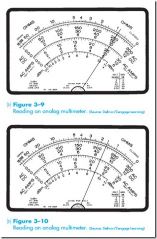
Notice that the three voltmeter scales use the primary numbers 3, 6, and 12 and are in multiples of 10 of these numbers. Because these numbers are in multiples of 10, it is an easy matter to multiply or divide the readings in your head by moving a decimal point. Remember that any number can be multiplied by 10 by moving the decimal point one place to the right, and any number can be divided by 10 by moving the decimal point one place to the left. For example, if the selector switch is set to permit the meter to indicate a voltage of 3 volts full-scale, the 300-volt scale would be used, and the reading divided by 100. The reading can be divided by 100 by moving the decimal point 2 places to the left. In Figure 3–9, the meter is indicating a voltage of 2.5 volts if the selector switch is set for 3 volts full-scale. The pointer is indicating a value of 250. Moving the decimal point 2 places to the left will give a reading of 2.5 volts. If the selector switch is set for a full-scale value of 30 volts, the meter shown in Figure 3–9 would be indicating a value of 25 volts. This reading is obtained by dividing the scale by 10 and moving the decimal point one place to the left.
Now assume that the meter has been set to have a full-scale value of 600 volts. The meter shown in Figure 3–10 is indicating a voltage of 440 volts. Since the full-scale value of the meter is set for 600 volts, use the 60-volt range and multiply the reading on the meter by 10. This can be done by moving the decimal point one place to the right. The pointer in Figure 3–10 is indicating a value of 44. If this value is multiplied by 10, the correct voltage reading becomes 440 volts.
There are three distinct steps that should be followed when reading a meter. Following the steps is especially important for someone who has not had a great deal of experience reading a multimeter. These steps are:
1. Determine what the meter indicates. Is the meter set to read a value of DC voltage, DC current, AC voltage, AC current, ohms? It is impossible to read a meter if you do not know what the meter is measuring.
2. Determine the full-scale value of the meter. The advantage of a multimeter is that it has the ability to measure a wide range of values and quantities. After it has been determined what quantity the meter is set to measure, it must then be determined what the range of the meter is. There is a great deal of difference in readings when the meter is set to indicate a value of 600 volts full-scale and when it is set for 30 volts full-scale.
If you are not sure of the voltage value being tested, always set the meter on its highest range and then reduce the range until the indicator moves up scale to a value that can be easily read. A meter can never be damaged by placing it on a high range setting and then reducing it, but it can be damaged by placing it on a low range setting and then connecting it to a high voltage.
Another consideration is the position of the indicator. Analog meters are more accurate at the upper end of the scale than at the lower end. If possible, adjust the range setting so that the indicator is more than halfway up the scale.
3. Read the meter. The last step is to deter- mine what the meter is indicating. It may be necessary to determine the value of the hatch marks on the meter face for the range the selector switch is set for. If the meter in Figure 3–8 is set for a value of 300 volts full- scale, each hatch mark has a value of 5 volts. If the full-scale value of the meter is 60 volts, however, each hatch mark has a value of 1 volt.
When reading a meter, always look straight at the indicator. Viewing the indicator from the side causes a parallax view and the reading will not be accurate. It is the same effect as produced when trying to determine the speed of an automobile by looking at the speedometer from the passenger seat. The only way to accurately determine the speed is to view the speedometer straight on, not from the side. Some meters have a mirror section on the meter face. This permits the person using the meter to line up the indication with the reflection behind it to ensure an accurate reading.
AMMETER
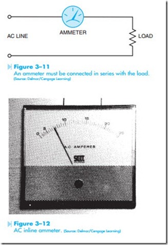
There are several different types of ammeters used to measure electric current. Clamp-on types are generally used in the field for troubleshooting, and inline ammeters are panel mounted. The inline ammeter, unlike the voltmeter, is a very-low-impedance device. Inline ammeters must be connected in series with the load to permit the load to limit the current flow, Figure 3-11.
An ammeter has a typical impedance of less than ohm. If this meter is connected in parallel with the power supply, the impedance of the ammeter is the only thing to limit the amount of current flow in the circuit. Assume that an ammeter with an impedance of .1 ohm is connected across a 240-volt AC line. The current flow in this circuit would be 2,400 amps (240/.1 = 2,400).The blinding flash of light would be followed by the destruction of the ammeter. Ammeters that are connected directly into the circuit as shown in Figure 3–11 are referred to as inline ammeters. Figure 3–12 shows an inline ammeter.
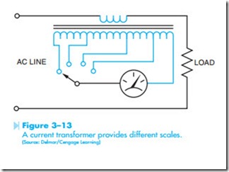
Notice that the meter in Figure 3–12 has several ranges. AC ammeters use a current trans- former to provide multiscale capability. The primary of the transformer is connected in series with the load, and the ammeter is connected to the secondary of the transformer. Figure 3–13 illustrates this type of connection. Notice that the range of the meter is changed by selecting different taps on the secondary of the current transformer. The different taps on the transformer provide different turns ratios between the primary and secondary of the transformer.
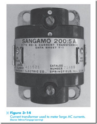
When a large amount of AC current must be measured, a current transformer is connected in to the power line. The ammeter is then connected to the secondary of the transformer. The AC amme- ters are designed to indicate a current of 5 amps, and the current transformer determines the value of line current that must flow to produce a current of 5 amps on the secondary of the transformer. The incoming line may be looped around the opening in the transformer several times to produce the proper turns ratio between the primary and the secondary windings. Figure 3–14 shows a transformer of this type. This type of connection is often used for panel meters mounted on large commercial units.
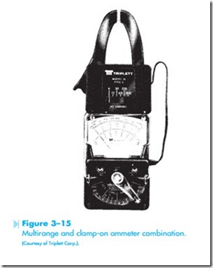
The type of ammeter used in the field by most air conditioning service technicians is the clamp-on type of ammeter similar to the one shown in Figure 3–15. To use this meter, the jaw of the meter is clamped around one of the conductors supplying power to the load. Figure 3–16 shows this connection. Notice that the meter is clamped around only one of the power lines. If the meter is clamped around more than one line, the magnetic fields of the wires cancel each other and the meter indicates zero.
This type of meter also uses a current transformer to operate the meter. The jaw of the meter is part of the core material of the transformer. When the meter is connected around the current-carrying wire, the changing magnetic field produced by the AC current induces a voltage into the current transformer. The strength of the magnetic field and its frequency determine the amount of voltage induced in the current transformer. Since 60 Hz is a standard frequency throughout the country, the amount of induced voltage is proportional to the strength of the magnetic field.
The clamp-on type of ammeter can have different range settings by changing the turns ratio of the secondary of the transformer just as the inline ammeter does in Figure 3–13. The primary of the current transformer is the conductor the ammeter is connected around. If the ammeter is connected around one wire as shown in Figure 3–16, the
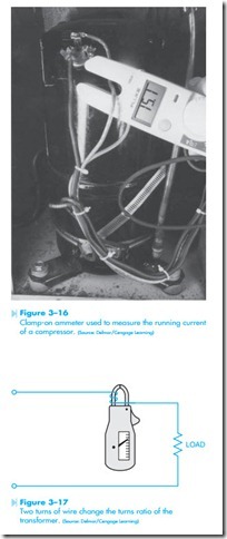
primary has one turn of wire as compared to the number of turns of wire in the secondary. If two turns of wire are wrapped around the jaw of the ammeter, the primary winding now contains two turns instead of one, and the turns ratio of the trans- former is changed, Figure 3–17. The ammeter will now indicate double the amount of current in the circuit. The reading on the scale of the meter would have to be divided by two to get the correct reading. For example, assume two turns of wire have been wrapped around the ammeter jaw, and the meter indicates a current of 3 amps. The actual current in this circuit is 1.5 amps (3 ÷ 2 = 1.5). The ability to change the turns ratio of a clamp-on ammeter can be very useful for measuring low currents such as those found in a control circuit. Changing the turns ratio of the transformer is not limited to wrapping two turns of wire around the jaw of the ammeter. Any number of turns of wire can be wrapped around the jaw of the ammeter and the reading will be divided by that number. If three turns of wire are wrapped around the jaw of the meter, the reading will be divided by three.
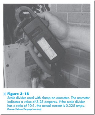
A very handy device can be made by wrapping 10 turns of wire around some core of nonmagnetic material, such as a thin piece of plastic pipe. Because the device is intended to be used for low current readings, the wire size does not have to be large. A #20 or #18 American Wire Gauge (AWG) wire is large enough. Plastic tape is used to secure the turns of wire to the core material, and two alligator clips are connected to the ends of the wire. This device is shown in Figure 3–18. To use this device, break connection in the circuit to be tested, and insert the 10 turns of wire using the alligator clips. The jaw of the ammeter is placed around the plastic core. The primary of the transformer now contains 10 turns of wire, and the scale factor can now be divided by a factor of 10. The correct ammeter reading is found by moving the decimal point one place to the left. If the ammeter has a low scale of 6 amps full-scale, it can now be used to measure .6 amps full-scale. This can be a real advantage when it is necessary to mea- sure control currents that may not be greater than
.2 amps under normal operating conditions.
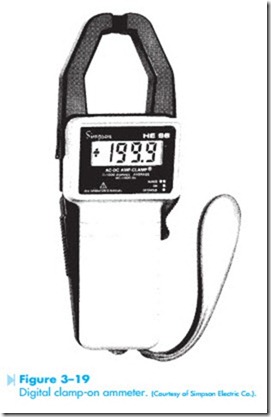
Some clamp-on ammeters use a digital read-out instead of a meter movement. A digital type meter is shown in Figure 3–19. The digital ammeters are
generally better for measuring low current values, but the 10 turn scale divider can be used with these ammeters also. Just remember to divide the reading shown by a factor of 10. The clamp-on ammeters discussed in this unit are intended to be used for measuring AC currents only, and will not operate if connected to a DC line. There are clamp-on type ammeters, however, that can be used to measure DC current.
Many clamp-on ammeters are designed to mea- sure AC volts and ohms as well as AC current. This makes the meter a more versatile instrument. When voltage or resistance is to be measured, a set of leads is attached to the meter.
OHMMETER
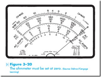
The ohmmeter is used to measure resistance. The common volt-ohm-milliammeter (VOM) contains an ohmmeter. The ohmmeter must provide its own power supply to measure resistance. This is done with batteries located inside the instrument. When resistance is to be measured, the meter must
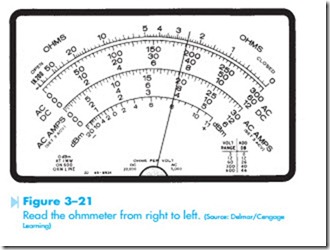
first be zeroed. Zeroing is done with the ohms adjust control located on the front of the meter. To zero the meter, connect the leads together and adjust the ohms adjust knob until the meter indicates 0 at the far right end of the scale, Figure 3–20. When the leads are separated, the meter will again indicate infinity resistance at the far left side of the meter scale. When the leads are connected across a resistance, the meter will again indicate up scale. Figure 3–21 shows a meter indicating a resistance of 25 ohms, assuming the range setting is R X 10.
Ohmmeters can have different range settings such as R X 1, R X 100, R X 1,000, or R X 10,000.
On the R X 1 setting, the resistance is measured straight off the resistance scale located at the top of the meter. If the range is set for R X 1,000, however, the reading must be multiplied by 1,000. The ohm- meter reading shown in Figure 3–21 would be indicating a resistance of 2,500 ohms if the range had been set for R X 1,000. Notice that the ohmmeter scale is read backward from the other scales. Zero ohms is located on the far right side of the scale, and maximum ohms is located at the far left side. It generally takes a little time and practice to read the ohmmeter properly.
Digital ohmmeters display the resistance in figures instead of using a meter movement. When using a digital ohmmeter, care must be taken to notice the scale indication on the meter. For example, most digital meters will display a K on the scale to indicate kilohms or an M to indicate megohms. (Kilo means 1,000, and mega means 1,000,000.) If the meter is showing a resistance of (.200 K), it means .2 X 1,000, or 200 ohms. If the meter indicates (1.65 M), it means 1.65 X 1,000,000, or 1,650,000 ohms.
The ohmmeter must never be connected to a circuit with power on. Because the ohmmeter uses its own internal power supply, it has a very low operat- ing voltage. If a meter is connected to power when it is set in the ohms position, it will probably damage or destroy the meter.
Related posts:
Incoming search terms:
- a voltmeter has a 5000 ohm per volt rating this means that on the 3 volt range the meter has 3 x 5000 or 15000 ohm of resistance what is the resistance on the 25 volt range?
- 0-300 volt of 12% and true value of 30 volt what is the range of
- Two voltmeter have the same range 0-400 V The internal impedance are 30 000 on Ms and 20 000 ohms If they are connected in series and 600 V be applied across them the reading are
- two voltmeters have the same range 0-400 V the internal impedances are 30 000 ohms and 20 000 ohms if they are connected in series and 600V be applied across them the readings are
- voltmeter 10000000 ohm
- what does ohm per volt mean
