Preliminary compressor stage design
By fixing the stage loading ψ, the flow coefficient φ, and the reaction R, the velocity triangles at the design condition are specified. However, as well as fixing the velocity triangles such that the compressor will achieve the required pressure rise with high efficiency, it is critically important for a compressor that it operates with an adequate stability margin. As will be explained later in this chapter, if too much pressure rise is demanded of a compressor it can become unstable and enter an unacceptable operating regime (stall or surge). The choice of the velocity triangle parameters is therefore a compromise between the best performance at the design condition and the sufficient operating range.
Many axial compressors are multistage devices and, for simplicity, repeating stages are initially assumed in which the velocity triangles for all stages are similar, the mean radius is constant, and the axial velocity through the machine is constant. In such machines, the flow coefficient, stage loading, and reaction are the same in every stage.
Note that this section only briefly covers the main preliminary design considerations and the associated mean-line analysis. If further details are needed, complete descriptions of the compressor design process can be found in Gallimore (1999) and Calvert and Ginder (1999).
Stage loading
The blades of a compressor behave like diffusers, each row of rotors and stators slowing down the local relative velocity (see Chapter 3). The amount of diffusion possible is limited, because if too much diffusion is demanded, the flow will separate from the blades leading to compressor stall or surge. DeHaller (1953) proposed that the relative velocity at exit from a blade row should be at least 72% of the inlet relative velocity for satisfactory performance. This is equivalent to limiting the pressure rise across each blade row and the maximum stage loading possible.
The stage loading ψ for a normal, or repeating, stage can be written as
where φ 5 cx/U is the flow coefficient.
The choice of stage loading at the compressor design point is critical. A value that is too low will lead to an excessive number of compressor stages to achieve a required pressure ratio. A value that is too high will limit the operating range of the compressor and increase the number of aero- foils needed to remove the risk of flow separation. As shown in Chapter 3, Lieblein’s diffusion fac- tor, DF, is a useful parameter for determining the blade pitch-chord ratio needed for acceptable performance. Based on Eq. (3.32), this can be written for a compressor rotor as
A larger stage loading requires more flow turning Δcθ and, therefore, to maintain an acceptable level of diffusion, the pitch-chord ratio of the blades must be reduced. This leads to a higher number of aerofoils, which tends to increase profile losses due to the higher wetted area and also leads to problems at high Mach numbers since the increased number of aerofoils will increase the likelihood of choking. For these reasons, pitch-to-chord ratios are typically in the range of 0.8-1.2 and the stage loading is limited to values around 0.4. However, more advanced compressor designs for aeroengines, where the need to reduce the number of stages is most pressing, may have higher stage loadings. A recent study by Dickens and Day (2011), looking at highly loaded axial compressors with stage loadings up to 0.75, shows that higher stage loading is possible but it inevitably leads to greater blade losses and, in particular, significant extra loss is generated by the blade pressure surface boundary layers.
Flow coefficient
From Eq. (5.17b), ψ 5 φ (tan β1 2 tan β2), which shows that for a fixed stage loading, as the flow coefficient increases, the flow turning required reduces. Hence, the diffusion through the blades is found to reduce as flow coefficient increases. Equally, for a fixed level of diffusion, the stage load- ing can increase as the flow coefficient rises. This suggests that a high flow coefficient is benefi- cial. In addition, higher values of flow coefficient correspond to higher inlet mass flow per unit area, which is a significant advantage as it implies a smaller diameter machine for a given mass flow.
However, in axial compressors, stage performance is often limited by Mach number effects and, for a fixed level of blade speed, high values of flow coefficient will lead to higher relative Mach number and potentially greater losses from choking and shock waves. Another disadvantage of a higher flow coefficient design concerns the tolerance of the compressor to nonuniform inflow. Compressors need to remain stable in the event of a disturbance in the inlet flow, and lower flow coefficient designs are found to absorb fluctuations more readily than high flow coefficient designs. The reasons for this are detailed in Smith (1958).
As a result of these considerations, typical values of φ used in designs are between 0.4 and 0.8 and often, for initial designs, 0.5 is chosen.
Reaction
The general definition of R for a compressor is the ratio of the rotor static enthalpy rise to the stage static enthalpy rise:
Eliminating β2 between Eqs (5.22) and (5.17c) gives an equation in ψ, φ, and R and the inter- stage swirl angle, α1
Equation (5.23) is identical to Eq. (4.14) derived for turbines, except for the sign convention. This equation shows that a higher reaction tends to reduce the stage loading, which is good for a compressor. However, stages having 50% reaction are widely used as the adverse (retarding) pressure gradient through the rotor rows and stator rows are equally shared. A 50% reaction also means that the rotor and stator blades will have similar shapes. Parametric design studies, as presented in Cumpsty (1989), suggest that the reaction is not such a critical parameter in determining compressor efficiency. However, Dickens and Day (2011) show that for stages with high stage loading, high reaction is required to achieve optimum efficiency. This appears to be necessary to reduce the pressure rise across the stator row which is more susceptible than the rotor to large separations. In many cases, though, the reaction is not a free design variable since it is determined by other factors. For example, in a design where the stage loading and flow coefficients have already been chosen, if the inlet swirl angle α1 is fixed, by having either an axial inlet flow or an inlet guide vanes, then the reaction must also be fixed (as indicated by Eq. (5.23)).
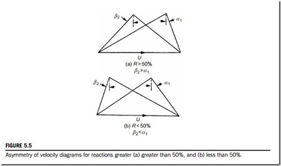
If R 5 0.5, then α1 5 β2 from Eq. (5.22), and the velocity diagram is symmetrical. The stage enthalpy rise is equally distributed between the rotor and the stator rows.
If R . 0.5, then β2 . α1 and the velocity diagram is skewed to the right as shown in Figure 5.5(a). The static enthalpy rise in the rotor exceeds that in the stator (this is also true for the static pressure rise).
If R , 0.5, then β2 , α1 and the velocity diagram is skewed to the left as shown in
Figure 5.5(b). Clearly, the stator enthalpy (and pressure) rise exceeds that in the rotor.
In advanced compressor designs, particularly in jet engine compressors, high reaction is com- mon and values between 0.5 and 0.8 are typical.
Interstage swirl
From Eq. (5.23), it can be seen that introducing positive swirl between the stages helps reduce stage loading. Positive swirl also reduces the relative inlet Mach number at inlet to the rotor. Therefore, advanced multistage compressors, particularly those within gas turbines, will often have an inter- stage swir1 angle of around 20-30o.
Blade aspect ratio
Once ψ, φ, and R are fixed at the design condition, the number of stages for a multistage compressor can be determined (see Example 5.3). Given a mass flow and blade speed, the mean radius of the compressor and the blade heights can also be calculated, using the calculations shown in Chapter 4. The overall compressor length and the number of blades can then be estimated by choosing suitable values of aspect ratio, H/l, for each blade row.
The choice of aspect ratio is important as this influences the blade losses and the stage stability
margin. Lower aspect ratios will tend to have greater losses due to increased wetted area and the build up of boundary layers. However, as shown in Koch (1997), lower aspect ratios tend to give
higher surge margin. This is why modern multistage compressors have lower aspect ratio values than might be expected, and 1-2 is typical.
The choice of aspect ratio, combined with the blade height, fixes the blade chord, l. The pitch- to-chord ratio, s/l, is determined by Eq. (5.18) combined with a choice of an acceptable level of diffusion factor, DF. With the blade chord known this then sets the number of blades in each row. Example 5.2 shows how this is done in practice for a low-speed compressor stage.
The overall compressor length depends on the axial gaps between blade rows. These will be set to limit the vibration and noise generated by rotor-stator interaction and spaces between the rows of about half an axial chord are typical.
EXAMPLE 5.2
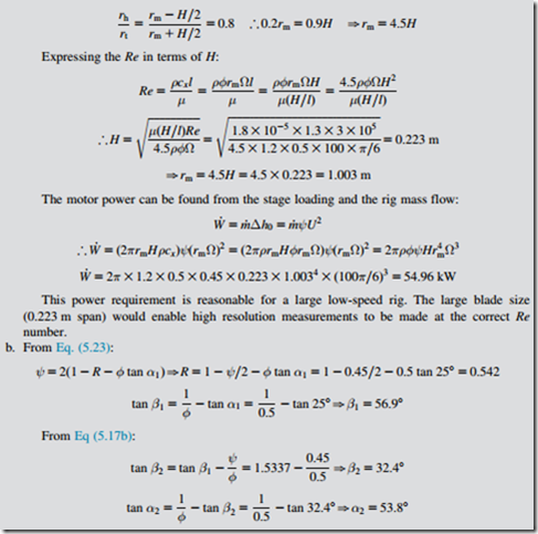
A low-speed single-stage rig is required to simulate a repeating stage of an air compressor with a flow coefficient of 0.5, a stage loading of 0.45 and 25o of preswirl at stage inlet. The motor that will drive the rig runs at 500 rpm. The aspect ratio of the rotor blade is to be 1.3 and its hub-to-tip radius ratio is 0.8.
a. If the Reynolds number needs to be 3 3 105, determine the mean radius for the rig, the rotor blade height and the motor power required. Use the following definition of Reynolds number based on midspan rotor chord:
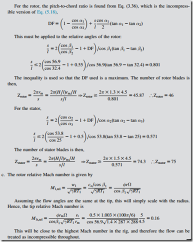
b. Calculate the stage reaction, the rotor relative flow angles, and the stator inlet flow angle. If the Lieblein diffusion factor for the rotor at the design point cannot exceed 0.55 and for the stator cannot exceed 0.5, determine the number of rotor and stator blades required. Assume that the stator aspect ratio is 1.5.
c. Confirm that the rig is low speed by estimating the rotor tip relative Mach number.
Solution
a. Use the hub-to-tip ratio to relate the mean radius to the blade height:


