Constant specific mass flow
Although there appears to be no evidence that the redistribution of the flow across blade rows is a source of inefficiency, it has been suggested by Horlock (1966) that the radial distribution of cθ for each blade row is chosen so that the product of axial velocity and density is constant with radius, i.e.,
where subscript m denotes conditions at r 5 rm. This constant specific mass flow design is the logical choice when radial equilibrium theory is applied to compressible flows as the assumption that cr 5 0 is then likely to be realized.
Solutions may be determined by means of a simple numerical procedure and, as an illustration of one method, a turbine stage is considered here. It is convenient to assume that the stagnation enthalpy is uniform at nozzle entry, the entropy is constant throughout the stage, and the fluid is a perfect gas. At nozzle exit under these conditions the equation of radial equilibrium, Eq. (6.20), can be written as
Using this set of equations, the procedure for determining the nozzle exit flow is as follows. Starting at r 5 rm, values of cm, αm, Tm, and ρm are assumed to be known. For a small finite interval Δr, the changes in velocity Δc, density Δρ, and temperature ΔT can be computed using Eqs (6.27), (6.28), and (6.29), respectively. Hence, at the new radius r 5 rm 1 Δr, the velocity c 5 cm 1 Δc, the density ρ 5 ρm 1 Δρ, and temperature T 5 Tm 1 ΔT are obtained. The corresponding flow angle α and Mach number M can now be determined from Eqs (6.26) and (6.28b), respectively. Thus, all parameters of the problem are known at radius r 5 rm 1 Δr. This procedure is repeated for further increments in radius to the casing and again from the mean radius to the hub.
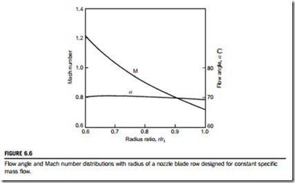
Figure 6.6 shows the distributions of flow angle and Mach number computed with this procedure for a turbine nozzle blade row of 0.6 hub-tip radius ratio. The input data used was
αm 5 70.4o and M 5 0.907 at the mean radius. Air was assumed at a stagnation pressure of 859 kPa and a stagnation temperature of 465oK. A remarkable feature of these results is the almost uniform swirl angle that is obtained.
With the nozzle exit flow fully determined the flow at rotor outlet can now be computed by a similar procedure. The procedure is a little more complicated than that for the nozzle row because the specific work done by the rotor is not uniform with radius. Across the rotor, using the notation of Chapter 4,
Eliminating successively dh0 between Eqs (6.30b) and (6.30c), dρ/ρ between Eqs (6.28) and (6.31), and finally dα from the resulting equations gives
The verification of Eq. (6.32) is left as an exercise for the diligent student.
Provided that the exit flow angle α3 at r 5 rm and the mean rotor blade speeds are specified, the velocity distribution, etc., at rotor exit can be readily computed from these equations.


