Connecting Risers to Mains
Many steam fitters connect risers directly to mains with a tee; although this method saves on extra labor and expense, it results in a more inefficient operation of the installation. When a tee is used, the condensation falls directly across the path of the steam flowing in the main and will be carried along and finally arrive at the radiator or convector with excess moisture. This problem is avoided with a 45° connection.
Using a 45° connection very effectively drains the condensation from the main, the path of the condensation being along the metal of the pipe and fittings instead of dripping directly into the steam.
The proper method of connecting a riser to a main where the riser has a direct connected drip pipe is by using a 45° connection downward. If the riser has no drip, the riser should be connected to the main with the leadoff being 45° upward connecting with a 45° elbow. The runout should pitch 1⁄2 inch per foot. Runouts over 8 feet in length, but with less than 1⁄2 inch per foot pitch, should be one size larger than specified in the pipe sizing tables.
If the condensation flows in the opposite direction to the steam, the runouts should be one size larger than the vertical pipe and pitched 1⁄4 inch per foot toward the main. If the runouts are over 8 feet in length, use a pipe two sizes larger than specified.
Connections to Radiators or Convectors
The connections to radiators and convectors must have a proper pitch when installed and be arranged so that the pitch will be main- tained under the strains of expansion and contraction. These con- nections are made by swing joints.
In two-pipe systems, radiators are connected either at the top and bottom opposite end or at the bottom and bottom opposite end. The top connection is not recommended for best performance. Short radiation may be top-supply and bottom-return connected on the same end.
Additional information about radiator and convector connections can be found in Chapter 2 of Volume 3 (“Radiators, Convectors, and Unit Heaters”).
Lift Fittings
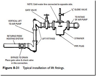
The lift fittings illustrated in Figure 8-31 are adapted for use on the main return lines of vacuum heating systems at points where it is desired to raise the condensation to a higher level. In operation, the
momentum of the water is maintained and assists in making the lift with minimum loss of vacuum. The lift fitting is constructed with a pocket at the bottom of the lift into which the water drains. As soon as sufficient water accumulates to seal this pocket, it is drawn to the upper portion of the return by the vacuum produced by the pump. The shape of the fitting is such that dirt and scale are usually swept along by the current. Cleanout plugs are provided for use if necessary. A second fitting in a reversed position is recommended for use at the top of the lift to prevent water from running back while the pocket is filled.
Drips
A steam main in any steam heating system may be dropped to a lower level without dripping if the pitch is downward with the direction of the steam flow. By the same token, the steam main in any system may be elevated if properly dripped.
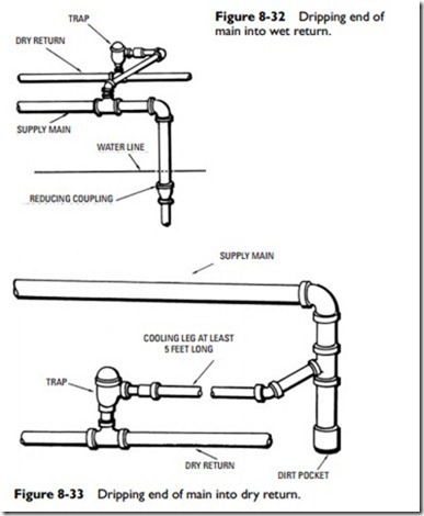
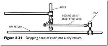
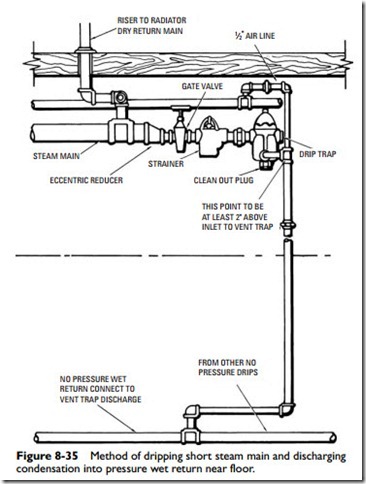
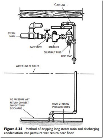
Various piping arrangements for dripping the main and riser are illustrated in Figures 8-32 through 8-39. Figure 8-39 shows a connection where the steam main is raised and the drain is to a wet return. If the elevation of the low point is above a dry return, it may be drained through a trap to the dry return in a two-pipe vapor, vacuum, or subatmospheric system.
A horizontal steam main can be run over an obstruction if a small pipe is carried below for the condensation with provisions for draining it.
In vacuum steam heating systems, drip traps for steam mains should be either thermostatic or combination float and thermo- static protected by dirt strainer or dirt pockets. Typical methods of making these connections are illustrated in Figures 8-40 through 8-43. The bases of supply risers are dripped through drip traps as
shown in Figures 8-44 and 8-45. Methods of connecting return risers are also shown.
In vapor steam heating systems, runouts to supply risers should be dripped separately into a wet return.
Dirt Pockets
On all systems employing thermostatic traps, dirt pockets should be located so as to protect the traps from scale and muck, which will interfere with their operation. Dirt pockets are usually made 8 to 12 inches deep.
Siphons
A siphon (see Figure 8-46) is used to prevent water from leaving the boiler due to lower pressure in a dry return. Condensation from the drip pipe falls into the loop formed by the siphon and, after it is filled, overflows into the dry pipe. The water will rise to different heights (G and H in the legs of the siphon) to balance the difference in pressure at these points.
If a dry return is used without a siphon, then water would be drawn from the boiler in sufficient amounts to balance the low pressure in the riser, filling the return and drip to approximately point M (see Figure 8-46).
Hartford Connections
Another method employed to prevent water leaving the boiler is the Hartford connection (or loop) on the wet return (see Chapter 15 of Volume 1, “Boilers and Boiler Fittings”).
Making Up Coils
In putting together lengths and return bends to form a coil heating unit, there is a right way and a wrong way to do the job. The essential requirement for the satisfactory operation of the coil is providing
for proper drainage. To obtain this, the pipes should not be parallel but should have a degree of pitch.
A pitch fitting should be used to obtain pitch in the coils rather than the so-called drunken thread method (see Figure 8-47). The drunken thread is obtained by removing the guide bushing from the stock and cutting the thread out of alignment. This gives a
poor joint—one that will eventually break because of corrosion. The corrosion is caused by the deep cut on one side of the pipe resulting from cutting the thread out of alignment.
