Regulation Techniques
Distribution utilities have several ways to control steady-state voltage. The most popular regulation methods include:
• Substation load tap-changing transformers (LTCs)
• Substation feeder or bus voltage regulators
• Line voltage regulators
• Fixed and switched capacitors
Most utilities use LTCs to regulate the substation bus and supplementary feeder regulators and/or switched capacitor banks where needed.
Taps on distribution transformers are another tool to provide proper volt- age to customers. Distribution transformers are available with and without no-load taps (meaning the taps are to be changed without load) with standard taps of ±2.5 and ±5%. Utilities can use this feature to provide a fixed boost for customers on a circuit with low primary voltage. This also allows the primary voltage to go lower than most utilities would normally allow. Remember, the service entrance voltage is most important. Most distribution transformers are sold without taps, so this practice is not widespread. It also requires consistency; an area of low primary voltage may have several trans- formers to adjust — if one is left out, the customers fed by that transformer could receive low voltage.
Voltage Drop Allocation and Primary Voltage Limits
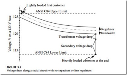
Most utilities use the ANSI C84.1 ranges for the service entrance, 114 to 126 V. How they control voltage and allocate voltage drop varies. Consider the voltage profile along the circuit in Figure 5.1. The substation LTC or bus regulator controls the voltage at the source. Voltage drops along the primary line, the distribution transformer, and the secondary. We must consider the customers at the start and end of the circuit:
• End — Heavily loaded — Low voltages are a concern, so we consider a heavily loaded transformer and secondary. The allocation across the secondary depends on the utility’s design practices as far as allowable secondary lengths and conductor sizes are concerned.
• Source — Lightly loaded — Near the source, we can operate the pri- mary above 126 V, but we must ensure that the first customer does not have overvoltages when that customer is lightly loaded. Commonly, utilities assume that the secondary and transformer drop to this lightly loaded customer is 1 V. With that, the upper primary voltage limit is 127 V.
In the voltage drop along the primary, we must consider the regulator bandwidth (and bandwidths for capacitors if they are switched based on voltage). Voltage regulators allow the voltage to deviate by half the band- width in either direction. So, if we have a 2-V bandwidth and a desired range of 7 V of primary drop, subtracting the 2-V bandwidth only leaves 5 V of actual drop (see Figure 5.1). Likewise, if we choose 127 V as our upper limit on the primary, our maximum set voltage is 126 V with a 2-V regulator bandwidth.
Normally, utilities use standardized practices to allocate voltage drop. Deviations from the standard are possible but often not worth the effort.
If we have an express feeder at the start of a circuit, we can regulate the voltage much higher than 126 V as long as the voltage drops enough by the time the circuit reaches the first customer.
Primary voltage allocation affects secondary allocation and vice versa. A rural utility may have to allow a wide primary voltage range to run long
circuits, which leaves little voltage drop left for the transformer and second- ary. Since rural loads are typically each fed by their own transformer, rural utilities can run the primary almost right to the service entrance. Using low- impedance distribution transformers and larger-than-usual transformers also helps reduce the voltage drop beyond the primary. For the secondary conductors, triplex instead of open wire and larger size conductors help reduce secondary drop. Utilities that allow less primary voltage drop can run longer secondaries.
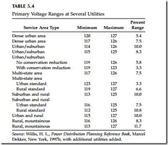
Utility practices on voltage limits on the primary range widely, as shown in Table 5.4. The upper range is more consistent — most are from 125 to 127 V — unless the utility uses voltage reduction (for energy conservation or peak shaving). The lower range is more variable, anywhere from 112 to 123 V. Obviously, the utility that uses a 112-V lower limit is not required to abide by the ANSI C84.1 limits.
Load Flow Models
Load flows provide voltage profiles that help when planning new distribu- tion circuits, adding customers, and tracking down and fixing voltage prob- lems. Most distribution load-flow programs offer a function to plot the voltage as a function of distance from the source.
We can model a distribution circuit at many levels of detail. Many utilities are modeling more of their systems in more detail. For most load flows,
utilities normally just model the primary. Modeling the secondary is occa- sionally useful for modeling specific problems at a customer. We can still have very good models with simplifications. Modeling long laterals or branches is normally a good idea, but we can lump most laterals together as a load where they tie into the main line. Modeling each transformer as a load is rarely worth the effort; we can combine loads together and maintain accuracy with some common sense. Most mainline circuits can be accurately modeled if broken into 10 to 20 sections with load lumped with each section. Of course, accurate models of capacitors and line regulators are a good idea.
Correctly modeling load phasing provides a better voltage profile on each phase. Unbalanced loads cause more voltage drop because of:
• Higher loop impedance — The impedance seen by unbalanced loads, the loop impedance including the zero-sequence impedance, is higher than the positive-sequence impedance seen by balanced loads.
• Higher current on the loaded phases — If the current splits unevenly by phases, the more heavily loaded phases see more voltage drop.
Utilities often do not keep accurate phasing information, but it helps improve load-flow results. We do not need the phasing on every transformer, but we will have better accuracy if we know the phasing of large single- phase taps.
Of the data entered into the load flow model, the load allocation is the trickiest. Most commonly, loads are entered in proportion to the transformer kVA. If a circuit has a peak load equal to the sum of the kVA of all of the connected transformers divided by 2.5, then each load is modeled as the given transformer size in kVA divided by 2.5. Incorporating metering data is another more sophisticated way to allocate load. If a utility has a trans- former load management system or other system that ties metered kilowatt- hour usage to a transformer to estimate loadings, feeding this data to the load flow can yield a more precise result. In most cases, all of the loads are given the same power factor, usually what is measured at the substation. Additional measurements could be used to fine-tune the allocation of power factor. Some utilities also assign power factor by customer class.
Most distribution load flow programs offer several load types, normally constant power, constant current, and constant impedance:
• Constant power load — The real and reactive power stays constant as the voltage changes. As voltage decreases, this load draws more current, which increases the voltage drop. A constant power model is good for induction motors.
• Constant current load — The current stays constant as the voltage changes, and the power increases with voltage. As voltage decreases, the current draw stays the same, so the voltage drop does not change.
• Constant impedance load — The impedance is constant as the voltage changes, and the power increases as the square of the voltage. As voltage decreases, the current draw drops off linearly; so the voltage drop decreases. The constant impedance model is good for incan- descent lights and other resistive loads.
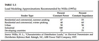
Normally, we can model most circuits as something like 40 to 60% constant power and 40 to 60% constant impedance (see Table 5.5 for one set of recommendations). Modeling all loads as constant current is a good approx- imation for many circuits. Modeling all loads as constant power is conser- vative for voltage drop.
Voltage Problems
Voltage complaints (normally undervoltages) are regular trouble calls for utilities. Some are easy to fix; others are not. First, check the secondary. Before tackling the primary, confirm that the voltage problem is not isolated to the customers on the secondary. If secondary voltage drop is occurring, check loadings, make sure the transformer is not overloaded, and check for a loose secondary neutral.
If the problem is on the primary, some things to look for include:
• Excessive unbalance — Balancing currents helps reduce voltage drop.
• Capacitors — Look for blown fuses, incorrect time clock settings, other incorrect control settings, or switch malfunctions.
• Regulators — Check settings. See if more aggressive settings can improve the voltage profile enough: a higher set voltage, more line drop compensation, and/or a tighter bandwidth.
These problems are relatively easy to fix. If it is not these, and if there is too much load for the given amount of impedance, we will have to add equipment to fix the problem. Measure the primary voltage (and if possible the loadings) at several points along the circuit. An easy way to measure the primary voltage is to find a lightly loaded distribution transformer and measure the secondary voltage. Measure the power factor at the substation. A poor power factor greatly increases the voltage drop.
Load flows are a good tool to try out different options to improve voltage on a circuit. If possible, match voltage profiles with measurements on the circuit. Measurements provide a good sanity check. Try to measure during peak load conditions. Regulator and capacitor controllers can provide extra information if they have data logging capability. Normally, we allocate the load for the model equally by transformer kVA. This may not always be right, and measurements can help “tweak” the model. A load flow can help determine the best course of action. Where do we need a supplementary line regulator? How many? Can fixed capacitors do the job? Do we need switched capacitors? Circuits with poor power factor are the best candidates for capacitors as they will help reduce line losses as well as improve voltage.
In addition to extra regulating equipment, consider other options. Some- times, we can move one or more circuit sections to a different feeder to reduce the loading on the circuit. If transformers have taps, investigate changing the transformer taps. Though it is expensive, we can also build new circuits, upgrade to a higher voltage, or reconductor.
Voltage Reduction
Utilities can use voltage adjustments as a way to manage system load. Voltage reduction can reduce energy consumption and/or reduce peak demand. Several studies have shown roughly a linear response relationship between voltage and energy use — a 1% reduction in voltage reduces energy usage by 1% (or just under 1%, depending on the study). Kirshner and Giorsetto (1984) analyzed trials of conservation voltage reduction (CVR) at several utilities. While results varied significantly, most test circuits had energy savings of between 0.5 and 1% for each 1% voltage reduction. Their regression analysis of the feeders found that residential energy savings were 0.76% for each 1% reduction in voltage, while commercial and industrial loads had reductions of 0.99% and 0.41% (but the correlations between load class and energy reduction were fairly small).
Voltage reduction works best with resistive loads because the power drawn by a resistive load decreases with the voltage squared. Lighting and resistive heating loads are the dominant resistive loads; these are not ideal resistive loads. For example, the power on incandescent lights varies as the voltage to the power of about 1.6, which is not quite to the power of 2 but close. Residential and commercial loads have higher percentages of resistive load. For water heaters and other devices that regulate to a temperature, reducing voltage does not reduce overall energy usage; the devices just run more often. Voltage reduction to reduce demand has even more impact than that on energy reduction. The most reduction occurs right when the voltage is reduced, and then some of the reduction is lost as some loads keep running longer than normal to compensate for lower voltage. For example, Priess and Warnock (1978) found that during a 4-h, 5% voltage reduction, the demand on one typical residential circuit dropped by 4% initially and dimin- ished to a 3% drop by the end of the 4-h period.
Voltage reduction works best on short feeders — those that do not have much voltage drop. On these, we can control reduction just through adjust- ments of the station LTC regulator settings. It is straightforward to set up a system where operators can change the station set voltage through SCADA. On longer circuits, we need extra measures. Some strategies include:
• Extra regulators — Extra regulators can help flatten the voltage profile along the circuit. Each regulator is set with a set voltage and com- pensation settings appropriate for a tighter voltage range. This approach is most appropriate for energy conservation. Controlling the regulators to provide peak shaving is difficult; the communica- tions and controls add significantly to the cost.
• Feeder capacitors — The vars injected by capacitors help flatten the voltage profile and allow a lower set voltage on the station LTC. On many circuits, just fixed capacitors can flatten the profile enough to reduce the station set voltage. McCarthy (2000) reported how Geor- gia Power used this strategy to reduce peak loads by 500 kW on circuits averaging approximately 18 MW.
• Tighter bandwidth — With a smaller regulator bandwidth, the voltage spread on the circuit is smaller. A smaller bandwidth requires more frequent regulator or LTC maintenance (the regulator changes taps more often) but not drastic differences. Kirshner (1990) reported that reducing the bandwidth from 3 to 1.5 V doubled the number of regulator tap changes.
• Aggressive line drop compensation — An aggressive line-drop com- pensation scheme can try to keep the voltage at the low end (say, at 114 V) for the last customer at all times. The set voltage in the station may be 115 to 117 V, depending on the circuit voltage profile. Aggressive compensation boosts the voltage during heavy loads, while trying to keep voltages low at the ends of circuits. During light loads, the station voltage may drop to well under 120 V. This strategy helps the least at heavy load periods, so it is more useful for energy conservation than for peak shaving. Aggressive com- pensation makes low voltages more likely at the end of circuits. If any of the planning assumptions are wrong, especially power fac- tor and load placement, customers at the end of circuits can have low voltages.
• Others — Other voltage profile improvement options help when implementing a voltage reduction program, although some of these options, such as reconductoring, undergrounding, load balancing, and increasing primary voltage levels, are quite expensive.
Related posts:
Incoming search terms:
- voltage regulation techniques
- techeniques for voltage regulation
- voltage regulation methods
- techniques for voltage regulation
- methods of voltage regulation
- method of decrease voltage regulation
- techniques to improve voltage regulation
- voltage regulation and methods of voltage regulation
- different voltage regulation techniques
- change in voltage regulation techniques


