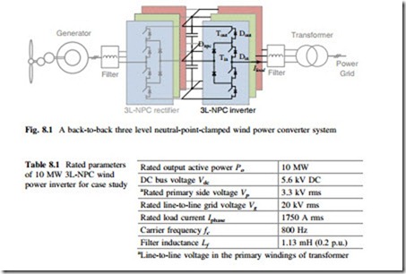
Wind Power Converter for Case Study
It is expected that 10 MW wind turbines with full-scale power converter will be the next long-term target to be conquered according to the technology trends. In most cases, the multi-level converter topologies will be demanded to handle such a high power with medium voltage ratings. As the most commercialized multilevel converter, three-level neutral-point-clamped (3L-NPC) topology seems to be a promising candidate, as shown in Fig. 8.1, where Tout represents the outer switch, Dout is the outer freewheeling diode, Tin is the inner switch, Din is the inner freewheeling diode, and Dnpc is the clamping diode. This configuration is selected for analysis in this special topic.
A 10 MW medium-voltage 3L-NPC wind power inverter is first designed for a case study. As summarized in Table 8.1, all of the power devices have the com- mutated voltage of 2.8 kV in order to utilize the dominant 4.5 kV high-power semiconductors available on the market, and the rated DC bus voltage can be determined at 5.6 kV. Normal phase-disposition sinusoidal-pulse-width-modulation method for 3L-NPC converter is applied, and the carrier frequency is typically designed to be 800 Hz in order to reach an acceptable switching loss in the power switching devices. The output filter inductance is designed to limit the maximum current ripple to 25 % of the rated current amplitude, and the filter capacitance is not taken into account. For simplicity of analysis and to keep the analytical focus on the power loss and thermal behavior of the power semiconductors, the power grid is considered as three ideal AC voltage sources and the DC bus capacitance is assumed high. The used generator and wind turbine models can be found from [1, 2].
Three power switching device solutions by using IGCT press-pack, IGBT press-pack, and IGBT module for the given 10 MW 3L-NPC wind power converter
are listed in Table 8.2, where the device ratings, configurations, total device numbers, and used device models are indicated respectively [3, 4]. It is noted that in order to justify and facilitate the comparison, each device solution is designed to handle the same load current up to 3.6 kA, thereby two 1.8 kA IGBT press-packs and three 1.2 kA IGBT modules have to be paralleled, due to the limits of maxi- mum available current rating for the corresponding power switching devices.
As it can be seen, in order to achieve 10 MW power conversion, the power semiconductors needed for the three device solutions are quite different: IGBT module solution consumes up to 80 % more device numbers than the other two press-pack solutions, this is mainly because of the maximum current rating limits for a single IGBT module. When taking into account the extra auxiliary parts like drives, fans, heat sink, wires, etc., the IGBT module solution may result in much lower power density and higher component counts, which may be unpreferable in the wind power application.
