Online Monitoring of Bushings and Lightning Arrestors
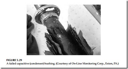
The deterioration of oil and paper insulation in HV equipment is a matter of continuous concern. Normal aging of HV equipment is a slow process that takes place over 30–40 years due to thermal, electrical, and environmental effects. With regard to transformer bushings, the most common type of bushing failure occurs due to a failure in the internal bushing capacitive layers. These failures occur slowly over time with one layer slowly failing and burn- ing through the kraft paper. A failed capacitive (condenser) bushing is shown in Figure 5.29. Premature failure on the other hand is often a relatively sudden process that is not detected by periodic off-line tests discussed in Sections
3.6.2 and 3.6.5 in Chapter 3. The use of the Scherring bridge technique using the voltage is very responsive to type of condition, and can detect these mil- livolt level changes. The millivolt level changes are far too small for an off- line test to detect and react to it in the early stages of failure. This prompted
the need for continuous online insulation condition monitoring to manage the risk of premature bushing failures and to initiate maintenance procedures based on the condition of the bushing insulation.
The On-Line Monitoring Corporation has developed PF Live Plus system for online PF (tan d) testing of transformer bushings and lightening arres- tors while the transformer remains energized. The PF calculation in the PF Live Plus system is based on the conventional Schering bridge used in labo- ratories. Data is acquired under software control from transducers connected to the bushing PF/capacitive tap associated with a transformer and then the data is compared to data from another electrical phase to produce a PF value. Damaged or deteriorated dielectric is associated with increased dielectric losses (I2R) with other sources of heating that may eventually fuel a mechanism of thermal runaway. The eventual breakdown of insulation is a rapid avalanche of failing dielectric layers. PF is a measure of dielectric losses, partial discharges, and treeing. High levels of partial discharge are reflected in the PF and are usually only present just after lightning or switching impulses and just before and during insulation failure.
The PF Live Plus is a continuous online monitoring system, for monitoring PF in HV capacitive bushings, and is now available with an optional leakage current monitor for HV lightning arresters. The system includes a minimum set of three sensors permanently connected to a series of capacitive bushing taps, or lightning arresters. It is based on the field proven SOS Tan Delta system. The system is capable of monitoring up to 32 direct-connected sensors, and up to 256 wireless sensors. The system acquires, analyzes, and trends data pertain- ing to AC insulation PF of bushings and/or HV current transformers, and leak- age current of lightning arresters. The PF Live Plus system can also interface to signals from other devices, or IED’s, such as: temperature sensors, DGA, or any 0–10 V DC, 10 V peak, 4–20 mA, or 0–1 mA signal, providing a single point access of transformer mounted sensors. Data can be downloaded on-site, or remotely. The concept of measuring PF is based on the derivation of the phase shift between two voltage signals. The method is similar to the standard bridge methods, but software is used for angle difference determination. The measure- ment of PF of insulation is accepted as part of well-established laboratory testing procedures to determine the quality of insulation at the factory before commis- sioning new and refurbished HV equipment. PF as a parameter is by nature a relatively slow-changing value and is an integral characteristic depending on
• Design, materials, and production technology
• Operating voltages and temperatures
• Aging of insulation related to design and operating conditions such as overvoltages, loading conditions, etc.
• Climatic/weather-related phenomenon
The system calculates the PF of a unit as a relative value compared with a ref- erence voltage from another unit in service, thereby eliminating the need for a standard capacitor. The reference device does not have to be associated with the same phase since PF Live Plus will automatically make the proper phase angle adjustments. Relative measurements and evaluation can reduce the effect of influences such as ambient temperature, operating voltages, loading conditions, different aging characteristics, different designs, operating conditions, etc. The system uses a principle of cross-referencing units in a closed loop to confirm all measurements and increase the confidence of isolating a defective unit. Because the system uses relative measurements, the minimum number of units to be monitored is three. All measurements are tested for integrity against three parameters: rms and mean of the signal, and the PF value calculated. Only measurements passing the integrity tests are stored in the database. The default monitoring period is once every 5 min. This setting can be changed from once a minute, to once per day. The sensors are config- ured into the graphical user interface by the user during installation. Each monitored device is entered into the database with an acquisition channel number, and descriptive text. The condition of each monitored device is dis- played on the monitor screen.
FRA: The off-line FRA test is discussed in Section 5.8.5. Recently, the National Electric Energy Testing, Research and Application Center (NEETRAC) has developed a method to perform this test while the transformer is in service. Online FRA data can provide an up-to-date condition assessment of large, essential transformers. Online FRA provides yet another tool to analyze the physical structure of the coils and their dielectric surroundings while the transformer remains in service. NEETRAC’s online FRA method uses normal system-switching operations, such as capacitor bank and reactor operations, along with lightning from local thunderstorms for the FRA test-signal source. NEETRAC’s patented technology can perform FRA signatures on transformer windings using a variety of input waveforms with different time and amplitude characteristics.
