Arc-Flash Hazard and Regulatory Requirements
The regulatory requirements of OSHA, NFPA 70, and NFPA 70E pertaining to a worker’s safety are described in Section 13.2. The regulatory requirements can be summarized as follows:
1. Determine the risk to personnel from exposure to incident energy released during an arc-flash event, i.e., the arc-flash hazard must be quantified.
2. Provide appropriate arc-flash hazard protection, i.e., correct PPE must be selected for nonprohibited work.
3. The arc flash assessment results must be documented and equipment labeled to inform and warn personnel of arc-flash hazard.
4. Personnel must be trained, understand the extent of arc-flash hazard, and take correct protective actions.
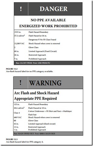
To quantify the hazard for each specific location, arc-flash analysis should be performed using either the IEEE 1584, IEEE Guide for Performing Arc-Flash Hazard Calculations, methodology or the alternate method given in 70E. The IEEE 1584 and 70E methodologies involve calculating available short-circuit currents for each location, determining the clearing time of protective relays and devices, equipment location type and working distance. See Sections 13.3.2 and 13.3.3 for more details on performing the arc-flash analysis study. The correct PPE category is selected based on the results of the arc-flash hazard analysis study. After completion of the steps 1 and 2, correct labeling is developed to label the equipment in accordance with NEC and 70E require- ments to warn personnel of the hazard. The labels that are generated from the arc-flash analysis programs are color coded to signify the severity of the danger of the incident energy available at the particular location. For exam- ple, the label color codes range from color green for category 0 (minimum severity) to color red (maximum severity) for which no PPE category is avail- able and where no work can be done on energized equipment. A sample of the two labels generated using an arc-flash analysis program is shown in Figures 13.2 and 13.3. It should be noted that the text and color of the label in Figure 13.2 signifies the “Danger” and states “energized work is prohibited” because the arc energy exceeds the 40 cal/cm2 for which no PPE is available.
The label shown in Figure 13.3 indicates PPE category 4 that the worker must use to perform work at this location. Both labels show the calculated flash protection boundary, incident energy, PPE category, glove classification, and shock protection boundaries per NFPA 70 E. The final step in this pro- cess is to give training to the employees on the arc-flash hazard, and how they should protect themselves.
Summary of NFPA 70, 70E, and OSHA Requirements
NFPA 70E and OSHA part 1910-132 require a hazard assessment for electrical equipment and selection of appropriate PPE for the employees if they are to work on energized equipment. Further, NFPA 70 (National Electric Code) requires that the equipment has to be labeled to show the available arc energy and the category of PPE the person needs to wear before working on the equipment. The following overview is offered for the reader in order to under- stand what is required by the above stated NFPA and OSHA requirements.
Overview of Arc-Flash Hazard
Arc-flash hazard is defined as a dangerous condition associated with the release of energy caused by an electric arc. The arc current creates a brilliant flash of light, a loud noise, intense heat, and a rapidly moving pressure wave. The products of arc-fault are ionized gases, metal vapors, molten metal drop- lets, and shrapnel that shower the immediate vicinity of the arcing fault. The electrical arc burns make up a substantial portion of injuries from electrical malfunctions. The extremely high temperatures of the electrical arc can cause fatal and major burns at distances of 5–10 ft from the arcing equipment. Therefore, the focus of industry on electrical safety and recognition of arc-flash burns as having great significance highlighted the need for protecting employees from all arc-flash hazards. The NEC-2008, Article 110-16 Flash protection, states in part that switchboards, panelboards, industrial control panels, and motor control centers that are in other than dwelling occupancies and are likely to require examination, adjustment, servicing, or maintenance while energized shall be field marked to warn qualified persons of potential electric arc-flash hazards. It is implied that flash protection is required when examining, adjusting, servicing, or maintaining energized equipment. The equipment shall be field marked (labeled) to warn qualified persons of potential electric arc-flash hazards. Let us now take a look at how the requirements for field labeling of equipment can be accomplished.
In order to generate an arc flash hazard label, an arc-flash hazard analysis study has to be conducted to determine the arc energy available at a given equipment. Therefore an arc-flash hazard analysis is performed in conjunction with the short-circuit study and protective device coordination study. Results of the short-circuit study are used to calculate the three-phase fault current from which the arcing fault current is determined. Results of protective device coordination study are used to determine the time required for the electrical protective devices to clear the arcing fault current conditions.
Results of both short circuit and protective device coordination studies are used to perform an arc-flash hazard analysis. Results of arc-flash hazard analysis are used to identify the flash protection boundary and the incident energy at assigned working distances for the electrical equipment. The flash protection boundary and the incident energy calculated in the arc-flash hazard analysis evaluation are based on taking credit for the protective relays and devices in removing the arc. Therefore it is important that these protective devices be kept in good working condition to maintain the validity of the arc- flash hazard analysis results. Readers will find useful information in Section 1.9 in Chapter 1, where a discussion is provided on the bases of maintenance and testing of protective devices. In view of the requirements for arc-flash hazard analysis, it has become even more important now to maintain and test breakers and protective devices on a regular basis to ensure their reliability.
Arc-Flash Analysis
The arc-flash analysis is conducted by using a software program specifically developed to do the arc-flash analysis. The arc-flash software programs are based on the methodologies given in IEEE-1584-2002 and the NFPA 70E methodologies. The arc-flash software program is intended to provide guidance based on the methodologies given in IEEE-1584–2002 and the NFPA 70E for the calculation of incident energy and arc-flash protection boundaries. The results obtained from the arc-flash software program can be used as a basis to develop strategies that have the potential of minimizing burn injuries. These strategies include specifying the rating of PPE, working only when the equipment is not energized, applying arc-resistance switchgear, and following other good engineering techniques and work practices. The guide for arc-flash analysis presented in the IEEE-1584-2002, is based on testing and analysis of the hazard presented by incident energy. The potentially hazardous effects of molten metal splatter, projectiles, pressure impulses, and toxic arc by-products were not considered in the analysis methodology of IEEE-1584-2002. The soft- ware programs based on the IEEE-1584-2002, provide analysis only for the hazards presented by incident energy and do not cover the potential hazards from molten metal splatter, projectiles, pressure impulses, and toxic arc by-products. The PPE listing documented in the result of the arc-flash software program are not intended to prevent all injuries but to mitigate the impact of an arc flash upon a person, if one should occur. The selection of a level of PPE is based on NFPA 70E, Table 130.7(C)(11) using the results of the arc-flash analysis. For conducting an arc-flash analysis, the following steps are required:
• Collect the system data
• Determine the system modes of operation
• Calculate the bolted fault currents
• Determine the arcing fault currents
• Determine protective device characteristics and the duration of the arcs (clearing time of the protective devices)
• Determine the system voltages and classes of equipment
• Select the working distances
• Determine the incident energy for all equipment
• Determine the flash boundary for all equipment
• Select PPE from the NFPA 70E-2004
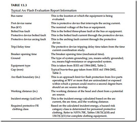
It should be noted that it takes an experienced engineer to implement the steps listed above for modeling the electrical power system, input the required system data, set the overcurrent relays and protective devices in the software program. After the short circuit and protective device coordination studies are completed then an arc flash hazard analysis study is conducted to calculate the various parameters of the arc flash hazard. The arc-flash software programs available on the market today will generate a report that provides detail information on the various aspects of arc flash hazard analysis. A typical arc flash evaluation report includes the information listed in Table 13.3.
Based on the calculated incident energy, a hazard risk category class is determined for personnel protective clothing. Refer to NFPA 70E, Tables 130.7(C)(10) and 130.7(C)(11) for complete clothing equipment.


