Distribution Transformers
From a few kVA to a few MVA, distribution transformers convert primary- voltage to low voltage that customers can use. In North America, 40 million distribution transformers are in service, and another one million are installed each year (Alexander Publications, 2001). The transformer connection deter- mines the customer’s voltages and grounding configuration.
Distribution transformers are available in several standardized sizes as shown in Table 4.2. Most installations are single phase. The most common
overhead transformer is the 25-kVA unit; padmounted transformers tend to be slightly larger where the 50-kVA unit is the most common.
Distribution transformer impedances are rather low. Units under 50 kVA have impedances less than 2%. Three-phase underground transformers in the range of 750 to 2500 kVA normally have a 5.75% impedance as specified in (ANSI/IEEE C57.12.24-1988). Lower impedance transformers provide better voltage regulation and less voltage flicker for motor starting or other fluctuating loads. But lower impedance transformers increase fault currents on the secondary, and secondary faults impact the primary side more (deeper voltage sags and more fault current on the primary).
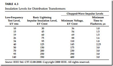
Standards specify the insulation capabilities of distribution transformer windings (see Table 4.3). The low-frequency test is a power-frequency (60 Hz) test applied for one minute. The basic lightning impulse insulation level (BIL) is a fast impulse transient. The front-of-wave impulse levels are even shorter-duration impulses.
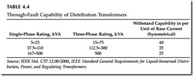
The through-fault capability of distribution transformers is also given in IEEE C57.12.00-2000 (see Table 4.4). The duration in seconds of the short- circuit capability is:
where I is the symmetrical current in multiples of the normal base current from Table 4.4.
Overhead and padmounted transformer tanks are normally made of mild carbon steel. Corrosion is one of the main concerns, especially for anything on the ground or in the ground. Padmounted transformers tend to corrode
near the base (where moisture and dirt and other debris may collect). Sub- mersible units, being highly susceptible to corrosion, are often stainless steel. Distribution transformers are “self cooled”; they do not have extra cooling capability like power transformers. They only have one kVA rating. Because they are small and because customer peak loadings are relatively short duration, overhead and padmounted distribution transformers have signif- icant overload capability. Utilities regularly size them to have peak loads exceeding 150% of the nameplate rating.
Transformers in underground vaults are often used in cities, especially for network transformers (feeding secondary grid networks). In this application,
heat can be effectively dissipated (but not as well as with an overhead or padmounted transformer).
Subsurface transformers are installed in an enclosure just big enough to house the transformer with a grate covering the top. A “submersible” trans-former is normally used, one which can be submerged in water for an extended period (ANSI/IEEE C57.12.80-1978). Heat is dissipated through the grate at the top. Dirt and debris in the enclosure can accelerate corrosion.
Debris blocking the grates or vents can overheat the transformer.
Direct-buried transformers have been attempted over the years. The main problems have been overheating and corrosion. In soils with high electrical and thermal resistivity, overheating is the main concern. In soils with low electrical and thermal resistivity, overheating is not as much of a concern, but corrosion becomes a problem. Thermal conductivity in a direct-buried transformer depends on the thermal conductivity of the soil. The buried transformer generates enough heat to dry out the surrounding soil; the dried soil shrinks and creates air gaps. These air gaps act as insulating layers that further trap heat in the transformer.


