Multilevel Converter Topologies
The multilevel converter is a power electronic circuit that can be operated in an inverter or rectifier mode. This chapter manly focuses on the inverter mode operation of the multilevel converters. In 1975, the concept of multilevel converter topology was proposed [5] and in the last few decades, several multilevel converter topologies have been patented [6, 7]. In order to achieve high voltage using low voltage switching devices, the multilevel converter topology uses a series of switching devices with low voltage dc sources. The proper control of the switching devices superimposes these multiple dc sources in a staircase form in order to achieve high voltage at the output.
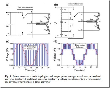
The renewable energy sources: wind turbine generators, solar PV arrays, and fuel cells can be used as the multiple dc voltage sources. With multilevel converter topology, the rated voltage of switching devices is much lower because the rated voltage of the switching devices depends on the rating of the dc voltage sources to which they are connected. A schematic circuit of a 3-phase 2-level conventional converter and a 3-phase m-level multilevel converter is shown in Fig. 1a, b. According to different switching states, it is possible to achieve high voltage level on output voltage by adding up the dc voltage sources compared with the 2-level inverters. According to Fig. 1c, it can be extracted that the quality of output voltage depends only on the sampling frequency, so higher sampling frequency means better voltage waveform. In case of multilevel converter output voltage waveform, as depicted in Fig. 1d, there is an additional factor to control the quality of output voltage waveform, i.e., the number of voltage levels.
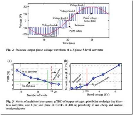
Synthesizing a staircase output voltage, which is closer to sinusoidal voltage reference compared with 2-level converter output, allows reduction in harmonic content of voltage waveforms which leads to the size and cost reduction of the power conversion systems. Each level of the staircase consists of a few PWM pulses, as shown in Fig. 2.
The frequency of the carrier signal of the PWM generator can be adjusted to control the quality of the output waveform like 2-level converter. However, the
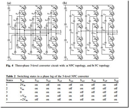
number of levels of the staircase waveform mostly affects the quality of the output voltage waveform. Figure 3a plots the total harmonic distortions (THDs) of 11 kV converters with different number of converter levels.
Although the number of semiconductor devices increases with the number of converter levels, the high-level converter enables to use low voltage devices, which are not only cheap but also mature in technology. Figure 3b plots the per unit price of switching devices with a rated current of 400 A. Therefore, the semiconductor cost of multilevel converters is lower than the equivalent 2-level converters operating at the same rating. Total semiconductor cost of high-level multilevel converters is reported in Sect. 4.
The highest voltage rating of commercially available insulated gate bipolar transistor (IGBT) is 6.5 kV; suitable for 2.54 kV or lower voltage converter systems with traditional 2-level converter topology. Table 1a summarizes the voltage ratings of commercially available IGBTs, where (Vcom@100FIT) is the device commutation voltage for a device reliability of 100 failures in time (FIT) due to cosmic radiation. The multilevel converter topology enables the possibility to develop medium and high voltage converters using commercially available
semiconductor devices. Table 1b summarizes the voltage handling capacity of 2- level and multilevel converters. Series connection of switching devices is a well- established method to develop medium voltage converter with 2-level converter topology. In order to reduce the effects of nonunique device characteristics and mismatch of driver circuit operations, the method uses snubber circuits and/or active gate controller, which increases switching losses.
The switching loss mostly depends on the commutation voltage of the switching devices, which can be much lower with multilevel converter topologies than that with 2-level converters. Moreover, multilevel converters require no switching aid circuits, which improve the commutation times. Therefore, multilevel converters give lower switching losses than that of 2-level converters. A power loss com- parison between MMC converter and 2-level converter was analyzed and it was reported that the switching losses of MMC converters are much lower than 2-level series connected converters operating at the same conditions [8].
Three different major multilevel converter structures have been reported in the literature: neutral point clamped (NPC), flying capacitor (FC), and MMC converter with separate dc sources.
Neutral Point Clamped Converter
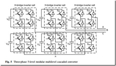
In order to increase the converter voltage rating without increasing the voltage rating of switching devices, the NPC converter topology was introduced in 1981 [9]. A 3-phase 5-level NPC converter circuit is shown in Fig. 4a.
A phase leg of a 5-level converter consists of four pairs of switching devices and three pairs of diode. Each switch in a pair works in complimentary mode and respective diodes pair provides access to the midpoint. If it is assumed that each auxiliary diode voltage rating is the same as the active switching device voltage rating, the number of diodes required for each phase will be (2m-4). An m-level NPC converter has an m-level output phase voltage and a (2m-1)-level output line voltage. Each of the three phases of the NPC converter shares a common dc-bus voltage, which has been subdivided by (m-1) capacitors into equal m-levels. Each phase leg of NPC converter requires (2m-2) active switching devices and the commutation voltage of each active switching device is (m-1) times lower than
the total dc-bus voltage. Table 2 summarizes the five switching states for a phase leg of a 5-level NPC converter.
In 1998, the NPC converter-based high power ac motor drive system was proposed [10]. In 2002, another application of NPC converter for high power medium voltage variable speed motor drives was proposed [11]. The NPC converter has also attracted significant attention for an interface between a high voltage dc (HVDC) transmission line and an ac transmission line [12]. The NPC converter topology has the opportunity to connect the neutral point to middle point of the dc-link, reducing the ground leakage currents, which enables this topology to form back to back connection. Therefore, in the last few years, the back to back NPC converters have also been largely utilized in the grid interfacing of renewable energy sources such as wind turbine generators and solar PV arrays. In 2006, a back to back NPC three-level converter-based wind power system was proposed [13]. In 2013, improved control scheme has been proposed to improve the steady- state and transient operation of back-to-back NPC converter [14].
However, when the number of converter levels is sufficiently high, the number of diodes required will make the system impractical to implement. In addition to the requirement of several auxiliary diodes, the capacitor voltage balancing is one
of the notable drawbacks of NPC topology, which will be critical in high-level converters. Unbalanced capacitor voltages may cause distortions in output wave- form and damage to switching devices due to over voltage breakdown of switching devices. For such a reason, many researchers are addressing their efforts in developing extra circuit and control algorithms [15], but still it is not more than 5- levels. Moreover, boost switch may limit the voltage and power rating of the converter. Therefore, this topology is not suitable for medium or high voltage applications, where higher number of levels are required.
Flying Capacitor Converter
In 1992, a new converter topology called FC converter was proposed [16]. The overall structure of FC converter can be comparable with that of the NPC con- verter except that the converter uses auxiliary capacitors, instead of using auxiliary diodes. The circuit topology of 3-phase 5-level FC converter is shown in Fig. 4b. A phase leg of a 5-level converter consists of four pairs of switching devices and three branches of capacitors. An m-level FC converter has an m-level output phase voltage and a (2 m-1)-level output line voltage. Each of the three phases of the FC converter may share a common dc-bus voltage similar to the NPC converter, which has been subdivided by (m-1) capacitors into equal m-levels. Each phase leg of FC converter requires (2 m-2) active switching devices and the commutation voltage of each active switching device is (m-1) times lower than the total dc-bus voltage. In addition to the (m-1) dc-bus capacitors, the m-level FC converter requires (m2-3 m ? 2)/2 auxiliary capacitors per phase if the voltage rating of the capacitors is equal to that of the active switching devices. One of the possible combinations of the switching states for a phase leg of a 5-level converter is summarized in Table 3.
Due to some features, controllability of real and reactive power, and capability to ride through short duration outages and voltage sags, the FC voltage source converters have found their application in power system applications. In 2002, FC multilevel voltage source converter-based unified power flow controller was proposed [17]. In 2007, 3-level FC multilevel converter-based high voltage direct current power transmission system was presented [18].
However, the number of auxiliary capacitors required is quadratically related to the number of levels. When the number of converter levels is sufficiently high, the number of capacitors required will make the system impractical to implement. The large number of capacitors not only increases converter size and weight but also significantly reduces the lifetime of the converter. Due to regulation of capacitor voltages, the FC multilevel converter requires complex control strategies. More- over, precharging of clamping capacitors with required voltage level may increase complexity and cost, and decrease the performances of the converter.
Modular Multilevel Cascaded Converter
In 1990, a single-phase MMC converter structure was presented for plasma stabilization applications [19] and in 1997, Robicon Corporation was presented a medium voltage high power 3-phase MMC converter for motor drive applications [20]. The complicated multi-winding phase-shifted power frequency transformer was used to deliver electric power to all the floating H-bridge inverter cells. In MMC converters, each phase leg consists of a series of modular single-phase full- bridge or H-bridge inverter cells. A 3-phase 5-level MMC converter circuit is illustrated in Fig. 5, which is wye connected. The 3-phase MMC converter can also be connected in delta.
Each isolated and balanced dc source is connected to a single-phase full-bridge or H-bridge inverter cell. The four switching devices of each H-bridge inverter cell can generate three different voltage outputs: +Vdc, 0, and –Vdc by connecting the isolated dc source to the ac output. The proper control of the switching devices superimposes the voltage outputs of all the H-bridge cells of a phase in a staircase
form in order to achieve high voltage at the converter output. Each H-bridge inverter cell contributes two voltage levels in output voltage. Similar to NPC and FC converters, an m-level MMC converter has also an m-level output phase voltage and a (2 m-1)-level output line voltage. As the NPC and FC multilevel converters, the MMC converter requires (2m-2) active switching devices per phase leg and the commutation voltage of each active switching device is (m-1) times lower than the total dc-bus voltage. Table 4 summarizes one of the possible switch combinations for a phase leg.
The component numbers of the MMC converters scale linearly with the number of levels, and individual modules are identical and modular in construction thereby enabling high-level number attainability. Furthermore, in the case of a fault in one of these modules, it is possible to replace it quickly and easily. Because of these special features the MMC converter topology has been considered as a possible candidate for medium and high voltage high power applications. In 1996, an MMC-based static synchronous compensator for reactive power control was presented [21] and in 1999, the converter was proposed for heavy duty electric and hybrid electric vehicles that have large electric motor drives [22]. A series of isolated batteries were used to deliver electric power to all the floating H-bridge inverter cells.


