Thermal Distribution Under Balanced LVRT
The thermal performance of power devices are closely related to the reliability of the converter, current rating of power devices, and the cost of the cooling system. Therefore, it is an important indicator for large-scale wind power converters. In order to conduct thermal performance evaluation, an appropriate thermal model should first be acquired.
Thermal impedance from junction to case Z(j−c) is modeled as a four-layer Foster RC network. Each of the thermal parameters can be found from the man- ufacturer’s datasheet and they are summarized in Table 12.2, where the thermal resistance Rth will decide the steady-state mean value of the junction temperature, and the thermal capacitance (with time constant τ) will decide the dynamic change or fluctuation of the junction temperature. The ambient temperature is set to 50 °C and considered constant during the operation of converter. However, it may be changed depending on the operation site.
It is noted that the separately packaged IGCT and diodes are chosen because of the limitation for available products, which can be found on the market. However, in a practical converter design, the IGCT/IGBT and its freewheeling diode are usually integrated and packaged together, the chip size for diode is usually about half of that for the IGCT/IGBT; accordingly, the thermal resistance of the diode from junction to heat sink is not consistent with its datasheet but set to twice the IGCT.
Normally, the thermal capacitance outside a power device from case to ambient are much larger compared to that inside a power device from junction to case in a properly designed cooling system. The larger thermal capacitance, which has longer time constant ranging from hundreds of milliseconds to hundreds of seconds, mostly decide the time to achieve steady-state junction temperature, and have no significant impact on the dynamic junction temperature fluctuation within a fun- damental cycle of the converter output (dozens of milliseconds). Therefore, it is efficient to make a simplification which ignores the relatively larger thermal capacitances in Z(c−h) and Z(h−a) to realize a faster thermal simulation. In megawatts power converter systems, separated heat sink is typically used and a good thermal decoupling among the power devices can be achieved, so the thermal resistance between the heat sink and ambient is considered small.
Based on the previous loss simulation results and thermal model, the junction temperature of the power devices in each of the converter solution can be investigated by the PLECS blockset in Simulink.
A. 3L-NPC
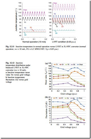
The simulated junction temperature in 3L-NPC converter under normal operation with 10 m/s wind speed and three- phase balanced LVRT condition with 0.05 p.u. grid voltage are shown in Fig. 12.11. It can be seen that the thermal distribution is quite unequal under both operation modes. The LVRT operation has higher junction temperate in all of the switching devices except the outer switch T1, and the maximum temperature which is located in the clamped diode Dnpc increases about 20 K compared to the normal operation at 10 m/s wind speed.
According to the important Coffin-Masson lifetime model, the junction temperature mean value Tm and the fluctuation amplitude ΔTj are two of the most important information for the reliability of power semiconductor devices; the simulated Tm and ΔTj of each switching device in 3L-NPC converter in relation to the grid voltage are shown in Fig. 12.12a, b respectively. The change in junction temperature keeps relatively smooth when the grid voltage is below 0.5 p.u., and becomes dramatic when the grid voltage is above 0.5 p.u. It is noted that there is a temperature rise in Dnpc and T1 when the grid voltage is around 0.7 p.u., which is due to the change in current phase angle and the fast growing switching loss in T1 and Dnpc.
B. 3L-HB
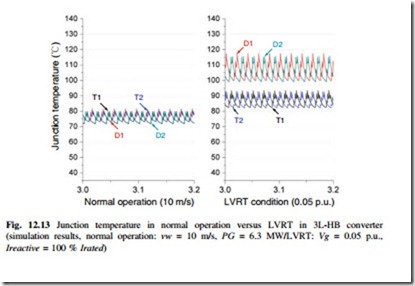
The simulated junction temperature in 3L-HB converter, under normal operation with 10 m/s wind speed and LVRT condition with 0.05 p.u. grid voltage is com- pared in Fig. 12.13. It can be seen that the junction temperature is equally dis- tributed among all the switching devices under normal operation, and significantly increases, especially in the diodes under LVRT. The maximum temperature which is located in the freewheeling diodes D1/D2 increases about 35 K compared to the normal operation with 10 m/s wind speed.
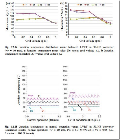
The simulated temperatures Tm and ΔTj in 3L-HB converter in relation to the grid voltage are shown in Fig. 12.14. It is interesting to see that the thermal distribution in 3L-HB topology under LVRT is much more equal than the 3L-NPC in Fig. 12.12, and both the junction temperature mean value and amplitude keep reducing when the grid voltage is above 0.5 p.u.
C. 5L-HB
The junction temperature in the 5L-HB converter under normal operation with 10 m/s wind speed and LVRT condition with 0.05 p.u. grid voltage are compared in Fig. 12.15, and the simulated Tm and ΔTj in 5L-HB converter in relation to the grid voltage are shown in Fig. 12.16.
It can be seen that the trends of thermal performance in the 5L-HB topology under LVRT is quite similar to that of the 3L-NPC topology, but the junction temperature keeps at a much lower level. This is because of the half current rating compared to the 3L-NPC topology.
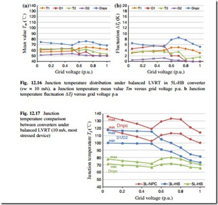
The junction temperature comparison of the most stressed power device in each of the converter topologies is shown in Fig. 12.17, in which the fluctuation range of the junction temperature is indicated. It can be seen that the 3L-NPC converter has the most stressed switching devices Dnpc among the three converter topologies, and the most extreme condition happens when the grid voltage is close to 0 p.u. (due to the large conduction losses) and 0.7 p.u. (due to the large switching losses). For the 3L-HB topology, it has better thermal performance compared to the
3L-NPC topology, especially when the grid voltage is above 0.5 p.u. The 5L-HB shows the best temperature performance among the three topologies, and shares the similar junction temperature changing trends as 3L-NPC converter. This also means that it has more potential to handle higher power or reduce the cost for cooling system and power semiconductors.


