In this special topic, three promising grid-side multilevel converters for 10 MW wind turbines are proposed and basically designed. The evaluation criteria will mainly aim at the utilization and thermal performances of power switching devices during various LVRT conditions. Studies regarding the converter output, as well as loss and thermal distributions under different grid voltage dips/wind speeds are presented and compared.
Promising Topologies and Basic Design
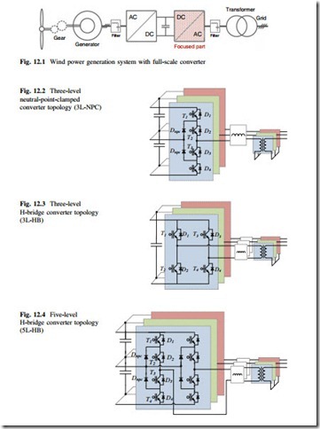
The concept and major parts of a variable speed wind turbine with full-scale power converters are shown in Fig. 12.1.
As mentioned before, the power capacity of a single wind turbine keeps climbing up even to 7 MW, and medium voltage (1–10 kV) would be interesting and needed to reduce the current rating in the wirings and switching devices under such a high power level. It is more difficult for the traditional two-level voltage source converter to achieve acceptable performance with the available switching devices. With the abilities of more output voltage levels, higher voltage amplitude and larger output power, multilevel converter topologies are becoming the most promising candidates in the application of full-scale power/medium-voltage wind power conversion.
Because the grid side converter in Fig. 12.1 is directly interfaced with the power grid, and plays a key role to comply with the stricter standards during grid faults, the discussions will mainly focus on this part of the generation system. Among various multilevel topologies, three of them are of interest (Figs. 12.2, 12.3, and 12.4):
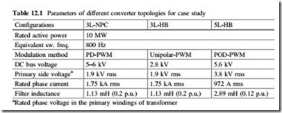
The basic design of each converter topology for a case study is as follows: All of the power switching devices have the commutated voltage of 2.8 kV in order to utilize the available and dominant 4.5 kV high-power IGCT/IGBT on the market,
then the DC bus and maximum output voltage of each configuration can be determined. The most commonly used carrier-based PWM method for each con- verter topology is applied and the equivalent switching frequency is typically designed to be 800 Hz in order to get an acceptable switching loss in the power devices. The output filter inductance is designed to limit the maximum current ripple to 25 % of the rated current amplitude, and the filter capacitance is not taken into account. The references of active and reactive current delivered by the inverter under different voltage dips are selected according to the German grid codes. The design parameters are summarized in Table 12.1. For simplicity of analysis, the power grid is considered as three ideal AC voltage sources, and the transformers are assumed ideal. The DC bus voltage during LVRT is assumed to be controlled at 110 % of the rated value by a DC bus chopper, which is a typical industrial solution used to absorb the active power from the generator.

