Stress Analysis of Converter Under LVRT
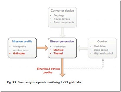
The ride-through operation of converter will significantly change the electrical behaviors compared to the normal conditions, and thereby result in quite different loading conditions of power devices. In this section, the electrical and thermal behaviors of converter under LVRT are going to be investigated. The relevant approaches for analysis are highlighted in Fig. 5.5. It can be seen that this section mainly focuses on the electrical and thermal stresses influenced by the mission profile, although the other stress-determining factors are needed to be involved in order to establish a proper operating condition for the converter.
5.2.1 Electrical Behaviors
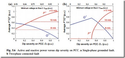
After the converter and grid conditions under grid faults are defined, the electrical behaviors of the given 3L-NPC converter can be simulated and specified. Figure 5.6 gives the profiles for the amount of active and reactive powers delivered by converter under various voltage dipping severities on Bus 1. The situations with one-phase and two-phase grid faults are shown in Fig. 5.6a, b, respectively. It can be seen that the delivered active/reactive powers by converter under the two types of grid faults are significantly different, especially when dip severity D1 is below
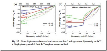
Figure 5.7 shows the phase angle displacement (between the load current of converter and grid voltage on Bus 2) with relation to the dipping severity on PCC. It is noted that the phase angle difference among the three phases of the converter becomes larger at smaller D1, and the maximum difference achieves 60° when D1 = 0 p.u. for both of the grid fault conditions. It can also be observed from Fig. 5.7 that the wind speeds have strong impacts to the phase angle of the converter under LVRT operation, especially when D1 is larger than 0.5 p.u..
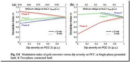
Figure 5.8 shows the modulation index of the given converter at various grid faults and dip severities on PCC. It can be seen that the two-phase grid fault leads to very large difference for modulation index among the three phases of converter (up to 0.7 difference when D1 = 0 p.u.). It is interesting to see that the wind speeds do not have strong impacts on the modulation index of converter under various LVRT conditions.
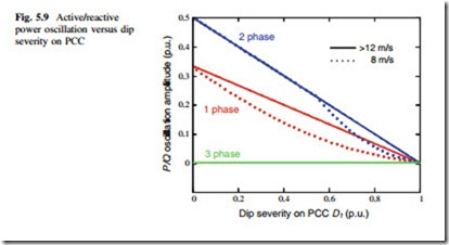
The active and reactive power oscillations under unbalanced grid voltage are inevitable if only positive sequence current is injected by the converter, and this problem can be explained by instantaneous power theory as detailed in [8]. Figure 5.9 shows the oscillation amplitude of the power delivered by the converter with relation to the dipping severity on PCC, where various grid faults and wind speed conditions are indicated. It can be seen that there is no power oscillation of the converter under the three-phase balanced grid fault, while the two-phase fault condition introduces larger power oscillation than the condition of one-phase fault at the same dipping severity on PCC. The maximum power oscillation amplitude achieves 0.5 p.u. at D1 = 0 when the two-phase grid fault is present.
The analytical functions and simulation examples for Figs. 5.6, 5.7, 5.8, and 5.9 are shown in Chap. 14. It can be expected that the dramatically different behaviors compared to the normal operation in respect to the delivered power, phase angles,
and modulation index under LVRT operations may lead to significantly different thermal loadings of power semiconductor devices.
Thermal Behaviors
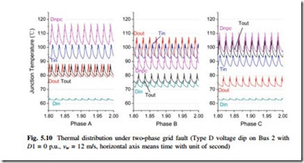
As an example, the junction temperatures for the three phases of 3L-NPC converter undergoing the extreme two-phase connected grid fault (Type D voltage dip on Bus 2 with D1 = 0 p.u., vw = 12 m/s) are shown in Fig. 5.10. It can be seen that the thermal loading behaviors in the three phases of the converter are totally different from each other.
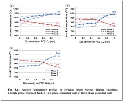
The mean junction temperature Tm of the switches and diodes under various dip severities and grid faults are summarized in Figs. 5.11 and 5.12, respectively. For the one-phase grid fault, Tout and Dnpc are the most stressed devices under the whole range of dipping severity, while for the two-phase and three-phase grid fault conditions, Tin and Dnpc are more stressed, when D1 is below 0.5 p.u..
Special attention should be given to the power device Tin, Dout, Din, and Dnpc under the LVRT operation of 3L-NPC. In fact those devices may have even higher junction temperature than in the cases of normal operation. (Up to 40 °C higher for Dout, 20 °C higher for Tin, 15 °C higher for Din, and 10 °C higher for Dnpc). This overloading should be taken into account when designing the power devices and heat sink system for the wind power converter.
In Chap. 12, the loading of power device in several promising multi-level converter topologies will be investigated based on the LVRT conditions.
