Introduction
When utility company power problems are discussed, most people immediately think of blackouts. The lights go out, and everything stops. With the facility down and in the dark, there is nothing to do but sit and wait until the utility company finds the problem and corrects it. This process generally takes only a few minutes. There are times, however, when it can take hours. In some remote locations, it can even take days.
Blackouts are, without a doubt, the most troublesome utility company problem that a facility will have to deal with. Statistics show that power failures are, generally speaking, a rare occurrence in most areas of the country. They are also short in duration. Studies have shown that 50% of blackouts last 6 s or less, and 35% are less than 11 min long. These failure rates usually are not cause for concern to commercial users, except where computer-based operations, transportation control systems, medical facilities, and communications sites are concerned.
When continuity of operation is critical, redundancy must be carried throughout the system. The site never should depend upon one critical path for ac power. For example, if the facility is fed by a single step- down transformer, a lightning flash or other catastrophic event could result in a transformer failure that would bring down the entire site. A replacement could take days or even weeks.
Blackout Effects
A facility that is down for even 5 min can suffer a significant loss of productivity or data that may take hours or days to rebuild. A blackout affecting a transportation or medical center could be life-threatening. Coupled with this threat is the possibility of extended power-service loss due to severe storm conditions. Many broad- cast and communications relay sites are located in remote, rural areas or on mountaintops. Neither of these kinds of locations are well-known for their power reliability. It is not uncommon in mountainous areas for utility company service to be out for extended periods after a major storm. Few operators are willing to take such risks with their business. Most choose to install standby power systems at appropriate points in the equipment chain.
The cost of standby power for a facility can be substantial, and an examination of the possible alternatives should be conducted before any decision on equipment is made. Management must clearly define the direct and indirect costs and weigh them appropriately. Include the following items in the cost-vs.-risk anal- ysis:
• Standby power-system equipment purchase and installation cost
• Exposure of the system to utility company power failure
• Alternative operating methods available to the facility
• Direct and indirect costs of lost uptime because of blackout conditions
A distinction must be made between emergency and standby power sources. Strictly speaking, emergency systems supply circuits legally designated as being essential for safety to life and property. Standby power systems are used to protect a facility against the loss of productivity resulting from a utility company power outage.
Standby Power Options
To ensure the continuity of ac power, many commercial/industrial facilities depend upon either two separate utility services or one utility service plus on-site generation. Because of the growing complexity of electrical systems, attention must be given to power-supply reliability.
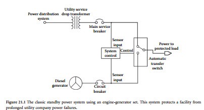
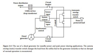
The engine-generator shown in Figure 21.1 is the classic standby power system. An automatic trans- fer switch monitors the ac voltage coming from the utility company line for power failure conditions. Upon detection of an outage for a predetermined period of time (generally 1 to 10 s), the standby generator is started; after the generator is up to speed, the load is transferred from the utility to the local generator. Upon return of the utility feed, the load is switched back, and the generator is stopped. This basic type of system is used widely in industry and provides economical protection against prolonged power outages (5 min or more).
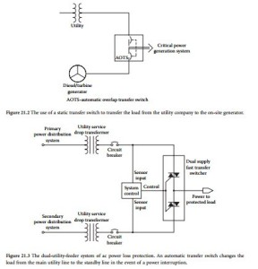
The transfer device shown in Figure 21.1 is a contactor-type, break-before-make unit. By replacing the simple transfer device shown with an automatic overlap (static) transfer switch, as shown in Figure 21.2, additional functionality can be gained. The overlap transfer switch permits the on-site generator to be synchronized with the load, making a clean switch from one energy source to another. This functionality offers the following benefits:
• Switching back to the utility feed from the generator can be accomplished without interruption in service.
• The load can be cleanly switched from the utility to the generator in anticipation of utility line problems (such as an approaching severe storm).
• The load can be switched to and from the generator to accomplish load shedding objectives (discussed later in this chapter).
Dual-Feeder System
In some areas, usually metropolitan centers, two utility company power drops can be brought into a facility as a means of providing a source of standby power. As shown in Figure 21.3, two separate utility ser- vice drops — from separate power-distribution systems — are brought into the plant, and an automatic transfer switch changes the load to the backup line in the event of a main-line failure. The dual-feeder system provides an advantage over the auxiliary diesel arrangement in that power transfer from main to
standby can be made in a fraction of a second if a static transfer switch is used. Time delays are involved in the diesel generator system that limit its usefulness to power failures lasting more than several minutes.
The dual-feeder system of protection is based on the assumption that each of the service drops brought into the facility is routed via different paths. This being the case, the likelihood of a failure on both power lines simultaneously is remote. The dual-feeder system will not, however, protect against areawide power failures, which can occur from time to time.
The dual-feeder system is limited primarily to urban areas. Rural or mountainous regions generally are not equipped for dual redundant utility company operation. Even in urban areas, the cost of bringing a second power line into a facility can be high, particularly if special lines must be installed for the feed. If two separate utility services are available at or near the site, redundant feeds generally will be less expensive than engine-driven generators of equivalent capacity.
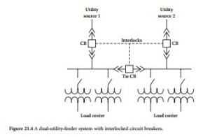
Figure 21.4 illustrates a dual-feeder system that utilizes both utility inputs simultaneously at the facility. Notice that during normal operation, both ac lines feed loads, and the “tie” circuit breaker is
open. In the event of a loss of either line, the circuit-breaker switches reconfigure the load to place the entire facility on the single remaining ac feed. Switching is performed automatically; manual control is provided in the event of a planned shutdown on one of the lines.
Peak Power Shaving
Figure 21.5 illustrates the use of a backup diesel generator for both standby power and peak power shaving applications. Commercial power customers often can realize substantial savings on utility company bills by reducing their energy demand during certain hours of the day. An automatic overlap transfer switch is used to change the load from the utility company system to the local diesel generator. The changeover is accomplished by a static transfer switch that does not disturb the operation of load equipment. This application of a standby generator can provide financial return to the facility, whether or not the unit is ever needed to carry the load through a commercial power failure.
Advanced System Protection
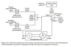
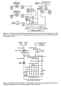
A more sophisticated power-control system is shown in Figure 21.6, where a dual feeder supply is coupled with a motor-generator set to provide clean, undisturbed ac power to the load. The m-g set will smooth over the transition from the main utility feed to the standby, often making a commercial power failure unnoticed by on-site personnel. A conventional m-g set typically will give up to 0.5 s of power fail ride-through, more than enough to accomplish a transfer from one utility feed to the other. This standby power system is further refined in the application illustrated in Figure 21.7, where a diesel generator has been added to the system. With the automatic overlap transfer switch shown at the generator output, this arrangement also can be used for peak demand power shaving.
Figure 21.8 shows a simplified schematic diagram of a 220 kW UPS system utilizing dual utility company feed lines, a 750 kVA gas-engine generator, and five dc-driven motor-generator sets with a 20- min battery supply at full load. The five m-g sets operate in parallel. Each is rated for 100 kW output. Only three are needed to power the load, but four are on-line at any given time. The fifth machine pro- vides redundancy in the event of a failure or for scheduled maintenance work. The batteries are always on-line under a slight charge across the 270 V dc bus. Two separate natural-gas lines, buried along different land routes, supply the gas engine. Local gas storage capacity also is provided.
Choosing a Generator
Engine-generator sets are available for power levels ranging from less than 1 kVA to several thousand kVA or more. Machines also can be paralleled to provide greater capacity. Engine-generator sets typically are classified by the type of power plant used:
• Diesel. Advantages: rugged and dependable, low fuel costs, low fire or explosion hazard. Disadvantages: somewhat more costly than other engines, heavier in smaller sizes.
• Natural and liquefied petroleum gas. Advantages: quick starting after long shutdown periods, long life, low maintenance. Disadvantage: availability of natural gas during areawide power failure subject to question.
• Gasoline. Advantages: rapid starting, low initial cost. Disadvantages: greater hazard associated with storing and handling gasoline, generally shorter mean time between overhaul.
• Gas turbine. Advantages: smaller and lighter than piston engines of comparable horsepower, rooftop installations practical, rapid response to load changes. Disadvantages: longer time required to start and reach operating speed, sensitive to high input air temperature.
The type of power plant chosen usually is determined primarily by the environment in which the system will be operated and by the cost of ownership. For example, a standby generator located in an urban area office complex may be best suited to the use of an engine powered by natural gas, because of the problems inherent in storing large amounts of fuel. State or local building codes can place expensive restrictions on fuel-storage tanks and make the use of a gasoline- or diesel-powered engine impractical. The use of pro- pane usually is restricted to rural areas. The availability of propane during periods of bad weather (when most power failures occur) also must be considered.
The generator rating for a standby power system should be chosen carefully and should take into consideration the anticipated future growth of the plant. It is good practice to install a standby power sys- tem rated for at least 25% greater output than the current peak facility load. This headroom gives a mar- gin of safety for the standby equipment and allows for future expansion of the facility without overloading the system.
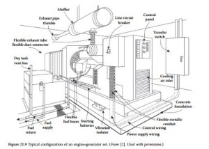
An engine-driven standby generator typically incorporates automatic starting controls, a battery charger, and automatic transfer switch. (See Figure 21.9.) Control circuits monitor the utility supply and start the engine when there is a failure or a sustained voltage drop on the ac supply. The switch transfers the load as soon as the generator reaches operating voltage and frequency. Upon restoration of the utility supply, the switch returns the load and initiates engine shutdown. The automatic transfer switch must meet demanding requirements, including:
• Carrying the full rated current continuously
• Withstanding fault currents without contact separation
• Handling high inrush currents
• Withstanding many interruptions at full load without damage
The nature of most power outages requires a sophisticated monitoring system for the engine-gener- ator set. Most power failures occur during periods of bad weather. Most standby generators are unat- tended. More often than not, the standby system will start, run, and shut down without any human intervention or supervision. For reliable operation, the monitoring system must check the status of the machine continually to ensure that all parameters are within normal limits. Time-delay periods usually are provided by the controller that require an outage to last from 5 to 10 s before the generator is started and the load is transferred. This prevents false starts that needlessly exercise the system. A time delay of 5 to 30 min usually is allowed between the restoration of utility power and return of the load. This delay permits the utility ac lines to stabilize before the load is reapplied.
The transfer of motor loads may require special consideration, depending upon the size and type of motors used at a plant. If the residual voltage of the motor is out of phase with the power source to which the motor is being transferred, serious damage can result to the motor. Excessive current draw also may trip overcurrent protective devices. Motors above 50 hp with relatively high load inertia in relation to torque requirements, such as flywheels and fans, may require special controls. Restart time delays are a common solution.
Automatic starting and synchronizing controls are used for multiple-engine-generator installations. The output of two or three smaller units can be combined to feed the load. This capability offers additional protection for the facility in the event of a failure in any one machine. As the load at the facility increases, additional engine-generator systems can be installed on the standby power bus.
Generator Types
Generators for standby power applications can be induction or synchronous machines. Most engine-generator systems in use today are of the synchronous type because of the versatility, reliability, and capability of operating independently that this approach provides [2]. Most modern synchronous generators are of the revolving field alternator design. Essentially, this means that the armature windings are held station- ary and the field is rotated. Therefore, generated power can be taken directly from the stationary armature windings. Revolving armature alternators are less popular because the generated output power must be derived via slip rings and brushes.
The exact value of the ac voltage produced by a synchronous machine is controlled by varying the current in the dc field windings, whereas frequency is controlled by the speed of rotation. Power output is controlled by the torque applied to the generator shaft by the driving engine. In this manner, the synchronous generator offers precise control over the power it can produce.
Practically all modern synchronous generators use a brushless exciter. The exciter is a small ac generator on the main shaft; the ac voltage produced is rectified by a three-phase rotating rectifier assembly also on the shaft. The dc voltage thus obtained is applied to the main generator field, which is also on the main shaft. A voltage regulator is provided to control the exciter field current, and in this manner, the field voltage can be precisely controlled, resulting in a stable output voltage.
The frequency of the ac current produced is dependent on two factors: the number of poles built into the machine, and the speed of rotation (rpm). Because the output frequency must normally be maintained within strict limits (60 or 50 Hz), control of the generator speed is essential. This is accomplished by providing precise rpm control of the prime mover, which is performed by a governor.
There are many types of governors; however, for auxiliary power applications, the isochronous governor is normally selected. The isochronous governor controls the speed of the engine so that it remains constant from no-load to full load, assuring a constant ac power output frequency from the generator. A modern system consists of two primary components: an electronic speed control and an actuator that adjusts the speed of the engine. The electronic speed control senses the speed of the machine and provides a feedback signal to the mechanical/hydraulic actuator, which in turn positions the engine throttle or fuel control to maintain accurate engine rpm.
The National Electrical Code provides guidance for safe and proper installation of on-site engine- generator systems. Local codes may vary and must be reviewed during early design stages.
UPS Systems
An uninterruptible power system is an elegant solution to power outage concerns. The output of the UPS inverter can be a sine wave or pseudosine wave. When shopping for a UPS system, consider the following:
• Power reserve capacity for future growth of the facility.
• Inverter current surge capability (if the system will be driving inductive loads, such as motors).
• Output voltage and frequency stability over time and with varying loads.
• Required battery supply voltage and current. Battery costs vary greatly, depending upon the type of units needed.
• Type of UPS system (forward-transfer type or reverse-transfer type) required by the particular application. Some sensitive loads may not tolerate even brief interruptions of the ac power source.
• Inverter efficiency at typical load levels. Some inverters have good efficiency ratings when loaded at 90% of capacity, but poor efficiency when lightly loaded.
• Size and environmental requirements of the UPS system. High-power UPS equipment requires a large amount of space for the inverter/control equipment and batteries. Battery banks often require special ventilation and ambient temperature control.
Standby Power-System Noise
Noise produced by backup power systems can be a serious problem if not addressed properly. Standby generators, motor-generator sets, and UPS systems produce noise that can disturb building occupants and irritate neighbors or landlords.
The noise associated with electrical generation usually is related to the drive mechanism, most commonly an internal combustion engine. The amplitude of the noise produced is directly related to the size of the engine-generator set. First, consider whether noise reduction is a necessity. Many building owners have elected to tolerate the noise produced by a standby power generator because its use is limited to emergency situations. During a crisis, when the normal source of power is unavailable, most people will tolerate noise associated with a standby generator.
If the decision is made that building occupants can live with the noise of the generator, care must be taken in scheduling the required testing and exercising of the unit. Whether testing occurs monthly or weekly, it should be done on a regular schedule.
If it has been determined that the noise should be controlled, or at least minimized, the easiest way to achieve this objective is to physically separate the machine from occupied areas. This may be easier said than done. Because engine noise is predominantly low-frequency in character, walls and floor/ceiling construction used to contain the noise must be massive. Lightweight construction, even though it may involve several layers of resiliently mounted drywall, is ineffective in reducing low-frequency noise. Exhaust noise is a major component of engine noise but, fortunately, it is easier to control. When selecting an engine-generator set, select the highest-quality exhaust muffler available. Such units often are identified as hospital-grade mufflers.
Engine-generator sets also produce significant vibration. The machine should be mounted securely to a slab-on-grade or an isolated basement floor, or it should be installed on vibration isolation mounts. Such mounts usually are specified by the manufacturer.
Because a UPS system or motor-generator set is a source of continuous power, it must run continuously. Noise must be adequately controlled. Physical separation is the easiest and most effective method of shielding occupied areas from noise. Enclosure of UPS equipment usually is required, but noise control is significantly easier than for an engine-generator because of the lower noise levels involved.
Nevertheless, the low-frequency 120 Hz fundamental of a UPS system is difficult to contain adequately; massive constructions may be necessary. Vibration control also is required for most UPS and m-g gear.
Batteries
Batteries are the lifeblood of most UPS systems. Important characteristics include the following:
• Charge capacity — how long the battery will operate the UPS
• Weight
• Charging characteristics
• Durability/ruggedness
Additional features that add to the utility of the battery include:
• Built-in status/temperature/charge indicator or data output port
• Built-in overtemperature/overcurrent protection with auto-reset capabilities
• Environmental friendliness
The last point deserves some attention. Many battery types must be recycled or disposed of through some prescribed means. Proper disposal of a battery at the end of its useful life is, thus, an important consideration. Be sure to check the original packaging for disposal instructions. Failure to follow the proper procedures could have serious consequences.
Research has brought about a number of different battery chemistries, each offering distinct advan- tages. Today’s most common and promising rechargeable chemistries include the following:
• Nickel cadmium (NiCd) — used for portable radios, cellular phones, video cameras, laptop com- puters, and power tools. NiCds have good load characteristics, are economically priced, and are simple to use.
• Lithium ion (Li-Ion) — typically used for video cameras and laptop computers. This battery has replaced some NiCds for high energy-density applications.
• Sealed lead-acid (SLA) — used for uninterruptible power systems, video cameras, and other demanding applications where the energy-to-weight ratio is not critical and low battery cost is desirable.
• Lithium polymer (Li-Polymer) — when commercially available, this battery will have the highest energy density and lowest self-discharge of common battery types, but its load characteristics will likely only suit low-current applications.
• Reusable alkaline — used for light-duty applications. Because of its low self-discharge, this battery is suitable for portable entertainment devices and other noncritical appliances that are used occasionally.
No single battery offers all the answers; rather, each chemistry is based on a number of compromises. A battery, of course, is only as good as its charger. Common attributes for the current generation of charging systems include quick-charge capability and automatic battery condition analysis and subsequent intelligent charging.
Terms
The following terms are commonly used to specify and characterize batteries:
• Energy density. The storage capacity of a battery measured in watt-hours per kilogram (Wh/kg).
• Cycle life. The typical number of charge-discharge cycles for a given battery before the capacity decreases from the nominal 100% to approximately 80%, depending upon the application.
• Fast-charge time. The time required to fully charge an empty battery.
• Self-discharge. The discharge rate when the battery is not in use.
• Cell voltage. The output voltage of the basic battery element. The cell voltage multiplied by the number of cells provides the battery terminal voltage.
• Load current. The maximum recommended current the battery can provide.
• Current rate. The C-rate is a unit by which charge and discharge times are scaled. If discharged at 1C, a 100 Ah battery provides a current of 100 A; if discharged at 0.5C, the available current is 50 A.
• Exercise requirement. This parameter indicates the frequency that the battery needs to be exercised to achieve maximum service life.
Sealed Lead-Acid Battery
The lead-acid battery is a commonly used chemistry. The flooded version is found in automobiles and large UPS battery banks. Most smaller, portable systems use the sealed version, also referred to as gelcell or SLA.
The lead-acid chemistry is commonly used when high power is required, weight is not critical, and cost must be kept low [3]. The typical current range of a medium-sized SLA device is 2 Ah to 50 Ah. Because of its minimal maintenance requirements and predictable storage characteristics, the SLA has found wide acceptance in the UPS industry, especially for point-of-application systems.
The SLA is not subject to memory. No harm is done by leaving the battery on float charge for a pro- longed time. On the negative side, the SLA does not lend itself well to fast charging. Typical charge times are 8 to 16 hours. The SLA must always be stored in a charged state because a discharged SLA will sulphate. If left discharged, a recharge may be difficult or even impossible.
Unlike the common NiCd, the SLA prefers a shallow discharge. A full discharge reduces the number of times the battery can be recharged, similar to a mechanical device that wears down when placed under stress. In fact, each discharge-charge cycle reduces (slightly) the storage capacity of the battery. This wear- down characteristic also applies to other chemistries, including the NiMH.
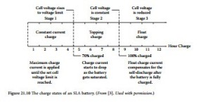
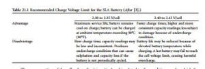
The charge algorithm of the SLA differs from that of other batteries in that a voltage-limit rather than current-limit is used. Typically, a multistage charger applies three charge stages consisting of a con- stant-current charge, topping-charge, and float-charge. (See Figure 21.10.) During the constant-current stage, the battery charges to 70% in about 5 hours; the remaining 30% is completed by the topping- charge. The slow topping-charge, lasting another 5 hours, is essential for the performance of the battery. If not provided, the SLA eventually loses the ability to accept a full charge, and the storage capacity of the battery is reduced. The third stage is the float-charge that compensates for self-discharge after the battery has been fully charged.
During the constant-current charge, the SLA battery is charged at a high current, limited by the charger itself. After the voltage limit is reached, the topping charge begins and the current starts to gradually decrease. Full-charge is reached when the current drops to a preset level or reaches a low-end plateau.
