Plant Maintenance
Maintenance of the facility electrical system is a key part of any serious energy-management effort. Perform the following steps on a regular basis:
• Measure the current drawn on distribution cables. Document the measurements so that a history of power demand can be compiled.
• Check terminal and splice connections to make sure they are tight.
• Check power-system cables for excessive heating.
• Check cables for insulation problems.
• Clean switchboard and circuit-breaker panels.
• Measure the phase-to-phase load balance at the utility service entrance. Load imbalance can result in inefficient use of ac power.
• Measure and chart the power factor of the load. Develop and post a simplified one-line schematic of the entire power net- work as well as other building systems, including heating, air- conditioning, security, and alarm functions. A mimic board is helpful in this process. Construct the mimic board control panel so that it depicts the entire ac power-distribution system. The board should have active indicators that show what loads or circuit breakers are turned on or off, what functions have been disabled, and key operating parameters, including input voltage, load current, and total kVA demand. Safety consider- ations require that machinery not be activated from the mimic board. Permit machinery to be energized only at the apparatus. As an alternative, remote control of machines can be provided, if a remote/local control switch is provided at the apparatus.
Environmental control systems should be monitored closely. Air-conditioning, heating, and ventilation systems often represent a significant portion of the power load of a facility. Computer-based data- logging equipment with process control capability can be of considerable help in monitoring the condition of the equipment. The logger can be programmed to record all pertinent values periodically and to report abnormal conditions.
Switchgear Maintenance
All too often, ac power switchgear is installed at a facility and forgotten — until a problem occurs. A care- less approach to regular inspection and cleaning of switchgear has resulted in numerous failures, including destructive fires. The most serious fault in any switchgear assembly is arcing involving the main power bus. Protective devices may fail to open, or open only after a considerable delay. The arcing dam- age to busbars and enclosures can be significant. Fire often ensues, compounding the damage.
Moisture, combined with dust and dirt, is the greatest deteriorating factor insofar as insulation is concerned. Dust or moisture are thought to account for as much as half of switchgear failures. Initial leakage paths across the surface of bus supports result in flashover and sustained arcing. Contact over- heating is another common cause of switchgear failure. Improper circuit-breaker installation or loose connections can result in localized overheating and arcing.
An arcing fault is destructive because of the high temperatures present (more than 6000°F). An arc is not a stationary event. Because of the ionization of gases and the presence of vaporized metal, an arc can travel along bare busbars, spreading the damage and sometimes bypassing open circuit breakers. It has been observed that most faults in three-phase systems involve all phases. The initial fault that triggers the event may involve only one phase, but because of the traveling nature of an arc, damage quickly spreads to the other lines.
Preventing switchgear failure is a complicated discipline, but consider the following general guide- lines:
• Install insulated busbars for both medium-voltage and low-voltage switchgear. Each phase of the bus and all connections should be enclosed completely by insulation with electrical, mechanical, thermal, and flame-retardant characteristics suitable for the application.
• Establish a comprehensive preventive maintenance program for the facility. Keep all switchboard hardware clean from dust and dirt. Periodically check connection points for physical integrity.
• Maintain control over environmental conditions. Switchgear exposed to contaminants, corrosive gases, moist air, or high ambient temperatures may be subject to catastrophic failure. Conditions favorable to moisture condensation are particularly perilous, especially when dust and dirt are present.
• Accurately select overcurrent trip settings, and check them on a regular basis. Adjust the trip points of protection devices to be as low as possible, consistent with reliable operation.
• Divide switchgear into compartments that isolate different circuit elements. Consider adding vertical barriers to bus compartments to prevent the spread of arcing and fire.
• Install ground-fault protection devices at appropriate points in the power-distribution system.
• Adhere to all applicable building codes.
Ground-System Maintenance
Out of sight, out of mind does not — or, at least, should not — apply to a facility ground system. Grounding is a crucial element in achieving reliable operation of electronic equipment. If a ground sys- tem has been buried for 10 years or more, it is due for an inspection. Soil conditions vary widely, but few areas have soil that permits a radial- or screen-based ground system to last much more than 15 years.
The method of construction and bonding of the ground network also can play a significant role in the ultimate life expectancy of the system. For example, ground conductors secured only by mechanical means (screws and bolts, crimping, and rivets) can quickly break down when exposed to even mild soil conditions. Unless silver-soldered or bonded using an exothermic method, such connections soon will be useless for all practical purposes.
The inspection process involves uncovering portions of the ground system to check for evidence of failure. Pay particular attention to interconnection points, where the greatest potential for problems exists. In some cases, a good metal detector will help identify portions of the ground system. It will not, however, identify breaks in the system. Portions of the ground system still will need to be uncovered to complete the inspection. Accurate documentation of the placement of ground-system components will aid the inspection effort greatly.
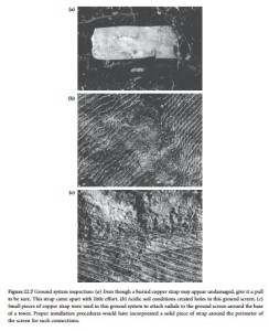
Check any buried mechanical connections carefully. Bolts that have been buried for many years may be severely deteriorated. Carefully remove several bolts, and inspect their condition. If a bolt is severely oxidized, it may twist off as it is removed. After uncovering representative portions of the ground system, document the condition of the ground through notes and photographs. These will serve as a reference point for future observation. The photos in Figure 22.7 illustrate some of the problems that can occur with an aging ground system. Note that many of the problems experienced with the system shown in the photographs resulted from improper installation of components in the first place.


