Analytical Solution of Junction Temperature with Chip Number Information
With the instantaneous loss model (9.4), (9.6) and thermal impedance model (9.11) (in which the chip number information is both included), it is possible to calculate the instantaneous junction temperature of switching devices by convoluting the loss and thermal impedance models as
However, this calculation is complicated and time consuming. Actually, only the temperature average mean value Tm and fluctuation amplitude ΔTj are related to the life-time of power devices by most of the reliability models for power semiconductors [6–10]. As a result, simplified junction temperature solutions, which can directly extract the information of Tm and ΔTj, have to be developed, and it is done in this special topic.
A. Simplified Solution for Tm
According to [15], the steady-state junction temperature mean value Tm is only related to the total thermal resistance as well as the average loss dissipation in the power devices. The Tm can be written as follows, where the chip number information is included:
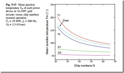
Fig. 9.15 Mean junction temperature Tm of each power device in 3L-NPC grid inverter versus chip numbers (normal operation,
The calculated mean junction temperature Tm with relation to the chip numbers N is shown in Fig. 9.15, in which each switching device in a switching arm of 10 MW 3L-NPC wind power inverter is indicated as an example.
According to the instantaneous power loss dissipation, as shown in Fig. 9.8, the time domain of losses in the most stressed devices is more or less sinusoidal distributed within a half fundamental cycle. On this case, it is not easy to acquire the fluctuation amplitude of junction temperature ΔTj, because the exact time when the junction temperature achieves its maximum/minimum value is hard to be derived by (9.12).
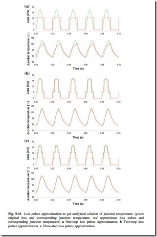
One possible simplification is to use square wave loss pulses which share the same loss-time area as the original sinusoidal loss distribution within a half fun- damental cycle. In this case, the loss is more constant and the time when the junction temperature achieves its maximum value can be determined.
In Fig. 9.16, three kind of loss pulses (one step, two steps, and three steps) which share the same loss-time area as the original sinusoidal-like losses are generated and applied to the same thermal impedance of IGBT module, and the corresponding junction temperatures are also indicated. It can be seen that the two-step loss pulses can achieve an acceptable consistency of junction temperature fluctuation with the original loss distribution.
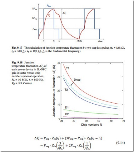
The more detailed two-step loss pulses and its resulting junction temperature are indicated in Fig. 9.17. It is relatively easy to calculate the temperature fluctuation amplitude ΔTj with the information of loss pulse amplitude and step time. The approximate function is shown as follows [17]:
The calculated junction temperature fluctuation ΔTj with relation to the chip numbers N is shown in Fig. 9.18, in which each switching device in a switching arm of 10 MW 3L-NPC inverter is indicated.
C. Temperature-Cost Profile of 3L-NPC Inverter
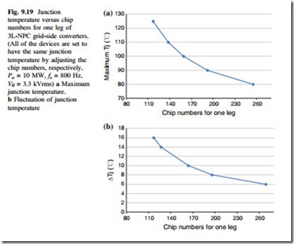
With the relationship between junction temperature and corresponding chip numbers for each of the power switching devices in Figs. 9.15 and 9.18, the same junction temperature (maximum or fluctuation) for each of the switching device can
be set by adjusting the chip numbers, respectively. The characteristics of the junction temperature for all of the switching devices with relation to the needed total chip numbers for one phase of the given 10 MW three-level Neutral-Point- Clamped wind power inverter can be plotted in Fig. 9.19.
It can be seen that Fig. 9.19 shows a unique performance profile of a given converter solution (topology, voltage rating, etc.); therefore, it is possible to unify and compare different converter solutions with this profile in a more sensible way. Because the junction temperature is close related to the life-time of power switching devices according to [6], and the chip numbers will decide the current rating and packaging of IGBT modules, the connection between reliability and cost of the power devices for a certain converter solution is thereby established.


