SUPERCONDUCTING MAGNETIC ENERGY STORAGE
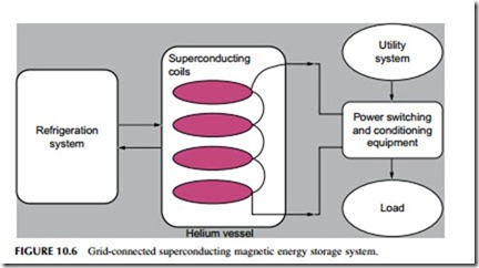
Superconductivity offers, in principle, the ideal way of storing electric power. The storage system comprises a coil of superconducting material that is kept extremely cold. Off-peak electricity is converted to DC and fed into the storage
ring where it stays, ready to be retrieved as required. Provided the system is kept below a certain temperature, electricity stored in the ring will remain there indefinitely without loss (Figure 10.6).
The key to the superconducting magnetic energy storage (SMES) device is a class of materials called superconductors. Superconductors undergo a fundamental change in their physical properties below a certain temperature called the transition temperature, which is a characteristic of each material. When a material is cooled below its transition temperature it becomes superconducting. In this state it has zero electrical resistance. This means that it will conduct a current with zero energy loss.
Unfortunately, the best superconducting materials are metallic alloys that only undergo this transition below 20 oK (-253 oC). Temperatures this low must be maintained by cooling the superconducting coil with liquid hydrogen or liquid helium—in either case an expensive process. In recent years scientists have discovered a new range of ceramic materials that become superconducting at relatively high temperatures, temperatures accessible by cooling with liquid nitrogen. (Liquid nitrogen boils at 98 oK, -175 oC.) Most of these materials have proved to be rather brittle ceramics that are difficult to work with but tech- niques are being found to exploit them. This is helping make superconductivity more economically attractive for a range of utility applications including storage.
Superconductors store DC current without loss but energy losses occur during the conversion of grid AC to DC and then from DC back to AC. The roundtrip efficiency is typically 90% for daily cycling but will be lower for long-term storage because of the energy required to maintain the coil below its transition temperature. There are also small continuous losses within the coil at the point where power is fed in and out. Startup time for a SMES system is around 5 msec.
When SMES devices were first proposed, they were conceived as massive energy storage rings of up to 1000 MW, similar in capacity to pumped storage hydropower plants. No such storage ring has ever been built, but smaller SMES devices are being used for grid support roles and this appears to be the main commercial market.
Modern technology has enabled smaller commercial SMES storage units with capacities between 100 kW and 100 MW to be constructed. The largest built to date can deliver 10 MW. The storage capacity of these commercial devices is between 10 kWh and 30 kWh, relatively low for utility storage but useful for very fast grid support functions.
One of the earliest SMES devices to be used commercially was commis- sioned by the U.S. Bonneville Power Administration in the 1980s. This unit had a storage capacity of 30 MJ and a power rating of 10 MW. The device could release 10 MJ of energy in one-third of a second to damp power swings on the Pacific Intertie. Today a typical commercial unit has a storage capacity of 3 MJ (0.83 kWh) and can deliver 3 MW of power for one second.
Costs
Although a few commercial SMES devices are available, costs have been difficult to establish. In general, the cost is relatively low per unit size (MW) but high in terms of storage capacity (MWh). For short-term grid stability duty, they appear to be competitive with other types of storage such as batteries, flywheels, and capacitors.
