Marine engines
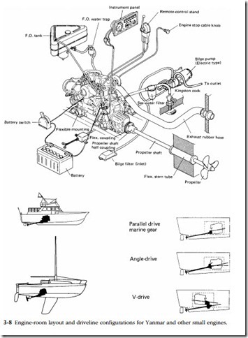
Because of the one-off nature of most small-boat construction, the technician is very much on his own when mounting an engine. Figure 3-8 provides an overview of the installation of Yanmar engines on sail and powered boats.
Mounts
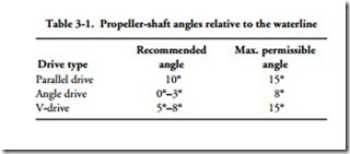
Inboard engines should be mounted level port-to-starboard and inclined no more than 15° off the horizontal (Table 3-1). Higher crankshaft angles reduce drive effi- ciency and increase the likelihood of oil starvation for engines with forward mounted oil-pump pickup tubes.
Your supplier will assist in determining propeller diameter, pitch, and style. As installed, the propeller should be at least one propeller diameter below the water- line and permit the engine to achieve maximum rated speed under full load at wide- open throttle. If the engine overspeeds by more than 5%, the propeller is undersized.
Once you have determined the inclination angle at which the engine will be installed, construct the bed, which should have as large a footprint as hull construc- tion permits. Leave room around the engine for servicing and, if possible, arrange matters so that the engine can be removed without structural alterations to the vessel. There must also be sufficient clearance between the flywheel cover/transmission and hull for compression of the flexible motor mounts.
Determine the height of the crankshaft centerline with the engine resting on its mounts. You should be able to get this data from the engine maker. The next and very critical operation is to mark holes for the prop shaft. Some yards use a laser alignment tool, while others rely upon the more traditional approach described here.
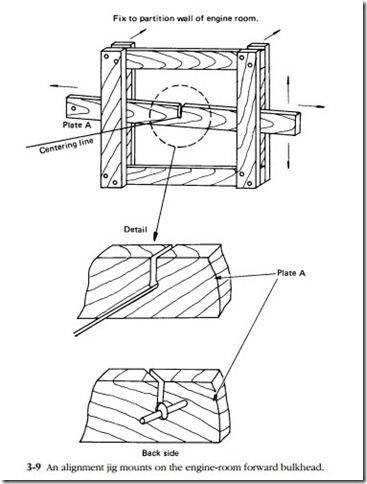
Construct a wooden jig, like the one shown in Fig. 3-9, and secure it to the for- ward engine-room bulkhead. Run a string from the jig to the stern box. Verify that the inclination is correct and that the string is on the vessel centerline. Measure the vertical distance between the string and hull to establish that the transmission, clutch, and other components have sufficient clearance.
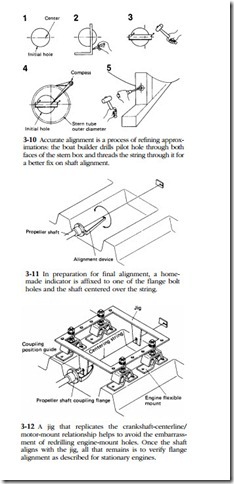
Using the string as a guide, mark stern-tube hole locations on the forward and aft sides of stern, or stuffing, box. Drill small holes where indicated on both sides of the box. Pass the string through these holes, which almost certainly will not center in the previously drilled holes. Figure 3-10 illustrates how the final hole dimensions are arrived at. Hole diameter should exactly match stern-tube diameter.
At this point, the crankshaft centerline and stern tube should be in fairly close alignment. Seal the stuffing-box holes with silicone, bolt down the stern tube, and secure the free end of the string to the center of the prop shaft. Using a fabricated marker, align the shaft with the string (Fig. 3-11).
The next step is to fabricate an engine-mounting jig with holes for the string at crankshaft location (Fig. 3-12). Place the jig on the engine bed and adjust the height and position of the mounts as necessary.
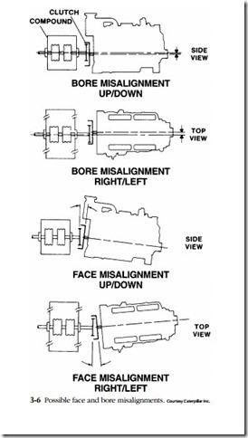
Finally, mount the engine and align the prop-shaft flange with the transmission flange as described previously for stationary engines.
Exhaust systems
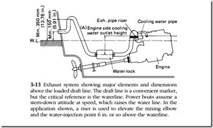
Wet exhaust systems reduce engine-room heat and simplify installation by allowing oil- and heat-resistant flexible hose to be used aft of the mixing elbow (Fig. 3-13). Basic specifications are:
• Exhaust outlet at transom—at least 6 in. above the loaded draft line.
• Elbow inboard of the transom—at least 14 in. higher than the draft line.
• Muffler—inboard of the elbow, with the outlet inclined about 8° off the horizontal.
• Water trap—located at the lowest point of the system between the muffler and engine. While a water trap is recommended for all installations, the backpressure developed by the unit can result in turbocharger surge. If this condition occurs, consult the engine manufacturer. It may be necessary to derate the engine by fitting a smaller propeller.
• Cooling-water injection point—6 in. or more above the draft line to prevent water in the hose from flowing back into the engine upon starting and after shutdown. When necessary, a riser can be used to raise the height of the mixing elbow.
