Power-Generating Systems
Electrical power can be produced in many ways, including chemical reactions, heat, light, or mechanical energy. Most electrical power produced today is through hydroelectric plants and nuclear energy, and by burning coal, oil, or natural gas. Fossil fuel and nuclear-fission plants use steam turbines to deliver the mechanical energy required to rotate large three-phase generators, which produce massive quantities of electrical power. Generators used in such facilities usually are classified as high-speed units, operating at 3600 rpm to produce a 60 Hz output frequency. Hydroelectric systems use hydraulic turbines, mounted vertically to intercept the flow of water to produce electrical energy. Most hydroelectric facilities use low- speed generators, operating at from 120 to 900 rpm to produce 60 Hz. It follows that a larger number of poles are required for a low-speed generator.
Fossil fuels, used as a source of heat, are burned to produce steam in a boiler system. The steam then drives one or more generators. Coal and coke are used commonly to produce energy in this manner. Other fossil fuel sources include oil and natural gas.
A nuclear power plant is basically a fossil fuel facility with a nuclear power source to produce heat and then steam. Nuclear fission is a complex process that results in the division of the nucleus of an atom into two nuclei. This splitting of the atom is initiated by bombardment of the nucleus with neutrons, gamma rays, or other charged particles.
A hydroelectric system is the simplest of all power plants. Flowing water from a reservoir is channeled through a control gate that directs water to the blades of a hydraulic turbine. The turbine, in turn, drives one or more generators. Although simple in design and efficient in operation, hydroelectric systems are limited by the availability of a water reservoir.
Concern about the burning of fossil fuels and the safety of nuclear power has led to the development of alternative fuel sources for turbine-driven power plants. Power-generating systems now in operation include:
• Geothermal systems, which utilize the heat of a molten mass in the interior of the earth to produce steam, which drives a turbine generator. Such systems are efficient and simple, but their placement is limited to areas of geothermal activity.
• Wind systems, which use a number of small generators mounted on supports and attached to propeller-type blades to intercept prevailing winds. Naturally, generator output is determined by wind activity, limiting the use of these systems on any large scale.
Significant variations in load requirements must be satisfied at different times by a generating plant. Because of wide variations in load demands, much of the generating capability of a facility may be unused during low-demand periods. Two mathematical ratios commonly are used to measure utility ser- vice:
• Load factor. The average load for a given period divided by the peak load for that same period.
• Capacity factor. The average load for a given period divided by the output capacity of the power plant.
Under ideal conditions, both the load factor and the capacity factor are unity (100%). Commercial power systems use a number of three-phase generators connected in parallel, and synchronized in phase, to sup- ply the load requirements.
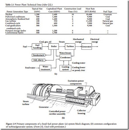
Table 2.1 lists general technical details for different types of common power plants.
Fossil Fuel Power Plants
The most frequently used fuels for large-scale power generation are oil, natural gas, and coal [3]. Figure illustrates the principal elements of a fossil fuel power plant. Fuel handling includes transport by rail, on ships, or through pipelines. A power plant usually maintains several days of fuel reserve at any one
time. Oil and gas are stored in large metal tanks, and coal is kept in open yards. The temperature of the coal layer must be monitored carefully to avoid self-ignition.
Oil is pumped and gas is fed to the burners of the boiler. Coal is pulverized in large mills, and the powder is mixed with air and transported by air pressure, through pipes, to the burners. The coal trans- port from the yard to the mills requires automated transporter belts, hoppers, and sometimes manually operated bulldozers.
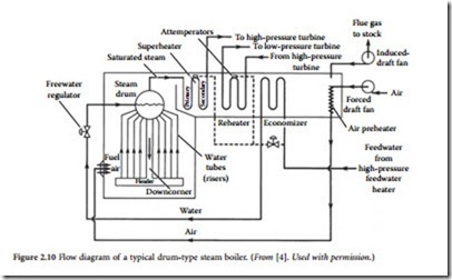
Two types of boilers are used in modern power plants: the subcritical water-tube drum-type and the supercritical once-through type. The former operates around 2500 psi, which is below the water critical pressure of 3208.2 psi. The latter operates above that pressure, at approximately 3500 psi. The super- heated steam temperature is about 1000°F (540°C) because of turbine temperature limitations.
A typical subcritical water-tube drum-type boiler has an inverted-U shape, as illustrated in Figure 2.10. On the bottom of the rising part is the furnace where the fuel is burned. The walls of the furnace are
covered by water pipes. The drum and the superheater are at the top of the boiler. The falling part of the U houses the reheaters, economizer (water heater), and air preheater, which is supplied by the forced-draft fan. The induced-draft fan forces the flue gases out of the system and sends them up the stack, which is located behind the boiler. This steam generator has three major systems:
• Fuel system. Fuel is mixed with air and injected into the furnace through burners. The burners are equipped with nozzles, which are supplied by preheated air and carefully designed to assure the optimum air-fuel mix. The fuel mix is ignited by oil or gas torches. The furnace temperature is around 3000°F.
• Air-flue gas system. Ambient air is driven by the forced-draft fan through the air preheater, which is heated by the high-temperature (600°F) flue gases. The air is mixed with fuel in the burners and enters the furnace, where it supports the fuel burning. The hot combustion flue gas generates steam and flows through the boiler to heat the superheater, reheaters, economizer, and other related systems. Induced-draft fans, located between the boiler and the stack, increase the flow and send the 300°F flue gases to the atmosphere through the stack.
• Water-steam system. Large pumps drive the feedwater through the high-pressure heaters and the economizer, which further increases the water temperature (400 to 500°F). The former is heated by steam removed from the turbine; the latter is heated by the flue gases. The preheated water is fed to the steam drum. Insulated tubes called downcomers are located outside the furnace and lead the water to a header. The header distributes the hot water among the risers. These water tubes line the furnace walls. The water tubes are heated by the combustion gases through both connection and radiation. The steam generated in these tubes flows to the drum, where it is separated from the water. Circulation is maintained by the density difference between the water in the downcomer and the water tubes. Saturated steam, collected in the drum, flows through the superheater. The superheater increases the steam temperature to about 1000°F. Dry superheated steam drives the high-pressure turbine. The exhaust from the high-pressure turbine goes to the reheater, which again increases the steam temperature. The reheated steam drives the low-pressure turbine.
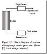
The typical supercritical once-through-type boiler concept is shown in Figure 2.11. The feedwater enters through the econ- omizer to the boiler, which consists of riser tubes that line the furnace wall. All the water is converted to steam and fed directly to the superheater. The latter increases the steam temperature above the critical temperature of the water and drives the turbine. The construction of these steam generators is more expensive than the drum-type units but has a higher overall operating efficiency.
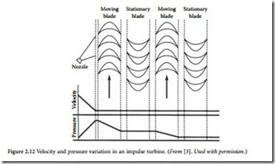
The turbine converts the heat energy of the steam into mechanical energy. Modern power plants typically use one
high-pressure and one or two lower-pressure turbines. High-pressure steam enters the high-pressure turbine to flow through and drive the turbine. The exhaust is reheated in the boiler and returned to the lower-pressure units. Both the rotor and the stationary part of the turbine have blades. The length of the blades increases from the steam entrance to the exhaust. Figure 2.12 shows the blade arrangement of an impulse-type turbine. Steam enters through nozzles and flows through the first set of moving rotor blades. The following stationary blades change the direction of the flow and direct the steam into the next set of moving blades. The nozzles increase the steam speed and reduce pressure, as shown in the figure. The impact of the high-speed steam, generated by the change of direction and speed in the moving blades, drives the turbine.
In a fossil fuel plant, the generator converts mechanical energy from the turbines into electrical energy. The stator typically has a laminated and slotted silicon steel iron core. The stacked core is clamped and held together by insulated axial through bolts. The stator winding is placed in the slots and consists of a copper-strand configuration with woven glass insulation between the strands and mica flakes, mica mat, or mica paper groundwall insulation. To avoid insulation damage caused by vibration, the groundwall insulation is reinforced by asphalt, epoxy-impregnated fiberglass, or Dacron. Most frequently, the stator is hydrogen-cooled; however, small units may be air-cooled, and very large units may be water-cooled. The solid steel rotor has slots milled along the axis. The multiturn copper rotor winding is placed in the slots and cooled by hydrogen. Cooling is enhanced by subslots and axial cooling passages. The rotor winding is restrained by wedges inserted in the slots.
The rotor winding is supplied by dc current, either directly by a brushless excitation system or through collector rings. The nondrive-end bearing is insulated to avoid shaft current generated by stray magnetic fields. The hydrogen is cooled by a hydrogen-to-water heat exchanger mounted on the genera- tor or installed in a closed-loop cooling system.
The condenser condenses turbine exhaust steam to water, which is pumped back to the steam generator through various water heaters. This condensation produces a vacuum, which is necessary to exhaust the steam from the turbine. The condenser usually is a shell-and-tube heat exchanger, where steam condenses on water-cooled tubes. Cold water is obtained from the cooling towers or other cooling systems. The condensed water is fed through a deaerator, which removes absorbed gases from the water. Next, the gas-free water is mixed with the feedwater and returned to the boiler. The gases absorbed in the water may cause corrosion and increase condenser pressure, adversely affecting efficiency. Older plants use a separate deaerator heater, whereas deaerators in modern plants are usually integrated in the condenser, where injected steam jets produce a pressure drop and remove absorbed gases.
Nuclear Power Plants
There are approximately 500 nuclear power plants operating around the world [3]. Close to 300 operate pressurized water reactors (PWRs), more than 100 are built with boiling-water reactors (BWRs), about 50 use gas-cooled reactors, and the rest are heavy-water reactors. In addition, a few fast breeder reactors are in operation. These reactors are built for better utilization of uranium fuel. The modern nuclear plant size varies from 100 to 1200 MW.
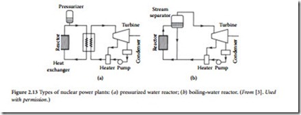
The general arrangement of a PWR power plant is shown in Figure 2.13a. The reactor heats the water from about 550 to approximately 650°F. High pressure, at about 2235 psi, prevents boiling. Pres- sure is maintained by a pressurizer, and the water is circulated by a pump through a heat exchanger. The heat exchanger evaporates the feedwater and generates steam, which supplies a system similar to a con- ventional power plant. The advantage of this two-loop system is the separation of the potentially radioac- tive reactor cooling fluid from the water-steam system.
The reactor core consists of fuel and control rods. Grids hold both the control and fuel rods. The fuel rods are inserted in the grid following a predetermined pattern. The fuel elements are Zircaloy-clad rods filled with UO2 pellets. The control rods are made of a silver, cadmium, and indium alloy protected by stainless steel. The reactor operation is controlled by the position of the rods. In addition, control rods are used to shut down the reactor. The rods are released and fall in the core when emergency shutdown is required. Cooling water enters the reactor from the bottom, flows through the core, and is heated by nuclear fission.
In the BWR, shown in Figures 2.13b and 2.14, the pressure is low (about 1000 psi). The nuclear reac- tion heats the water directly to evaporate it and produce wet steam at about 545°F. The remaining water is recirculated and mixed with feedwater. The steam drives a turbine that typically rotates at 1800 rpm. The
rest of the plant is similar to a conventional power plant. Figure 2.14 shows all the major components of the reactor. The fuel and control rod assembly is located in the lower part. The steam separators are above the core, and the steam dryers are at the top of the reactor. The reactor is enclosed by a concrete dome.
Hydroelectric Power Plants
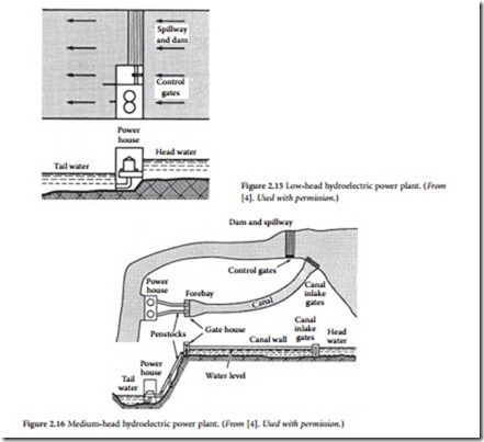
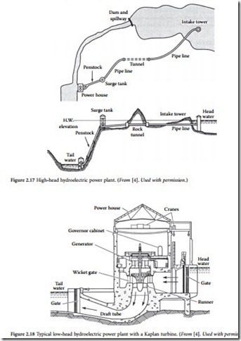
Hydroelectric power plants convert energy produced by a water head into electric energy [3]. The head is produced by building a dam across a river, which forms the upper-level reservoir. In the case of low head, the water forming the reservoir is fed to the turbine through the intake channel or the turbine is inte- grated in the dam. The latter arrangement is shown in Figure 2.15. Penstock tubes or tunnels are used for medium-head and high-head plants, as shown in Figure 2.16 and Figure 2.17, respectively. The spillway regulates the excess water in the reservoir by opening gates at the bottom of the dam or permitting over- flow on the spillway section of the dam. The water discharged from the turbine flows to the lower or tail water reservoir, which is usually a continuation of the original water channel.
High-head plants are built with impulse turbines, where the head-generated water pressure is converted into velocity by nozzles and the high-velocity water jets drive the turbine runner. Low- and medium-head installations are built with reaction-type turbines, where the water pressure is mostly con- verted to velocity in the turbine. The two basic classes of reaction turbines are the propeller or Kaplan
type, mostly used for low-head plants, and the Francis type, primarily used for medium-head plants. The cross section of a typical low-head Kaplan turbine is shown in Figure 2.18.
The vertical shaft turbine and generator are supported by a thrust bearing immersed in oil. The gen- erator is in the upper, watertight chamber. The turbine runner has 4 to 10 propeller types and adjustable- pitch blades. The blades are regulated from 5 to 35° by an oil-pressure-operated servomechanism. The water is evenly distributed along the periphery of the runner by a concrete spiral case and regulated by adjustable wicket blades. The water is discharged from the turbine through an elbow-shaped draft tube. The conical profile of the tube reduces the water speed from the discharge speed of 10 to 30 ft/s to 1 ft/s to increase turbine efficiency.
The hydrogenerator is a low-speed (usually 120 to 360 rpm) salient-pole machine with a vertical shaft. The typical number of poles ranges from 20 to 72. They are mounted on a pole spider, which is a welded, spoked wheel. The spider is mounted on the forged steel shaft. The poles are built with a laminated iron core and stranded copper winding. Damper bars are built in the pole faces. The stator is built with a slotted, laminated iron core that is supported by a welded steel frame. Windings are made of stranded conductors insulated between the turns by fiberglass or Dacronglass. The ground insulation is formed from multiple layers of mica tape impregnated with epoxy or polyester resins. Older machines use asphalt and mica tape insulation, which is sensitive to corona-discharge-caused insulation deterioration.
Direct water cooling is used for very large machines, whereas the smaller ones are air- or hydrogen-cooled. Some machines use forced-air cooling with an air-to-water heat exchanger. A braking system is installed in larger machines to stop the generator rapidly when necessary.
