Line Conditioner
A line conditioner combines the functions of an isolation transformer and a voltage regulator in one unit. The three basic types of line conditioners for DP applications are
• Linear amplifier correction system. As illustrated in Figure 14.15, correction circuitry compares the ac power output to a reference source, derived from a 60 Hz sine wave generator. A correction voltage is developed and applied to the secondary power winding to cancel noise and voltage fluctuations. A box shield around the primary winding provides common-mode impulse rejection
(80 to 100 dB typical). The linear amplifier correction system is effective and fast, but the overall regulating range is limited.
• Hybrid ferroresonant transformer. As shown in Figure 14.16, this system consists of a ferroresonant transformer constructed using the isolation techniques discussed in Section 15.4.2. The box and Faraday shields around the primary and compensating windings give the transformer essentially the characteristics of a noise-attenuating device, while preserving the voltage-regulating charac- teristics of a ferroresonant transformer.
• Electronic tap-changing, high-isolation transformer. This system is built around a high-attenuation isolation transformer with a number of primary winding taps. SCR pairs control voltage input to each tap, as in a normal tap-changing regulator. Tap changing also can be applied to the secondary, as shown in Figure 14.17. The electronic tap-changing, high-isolation transformer is an efficient design that effectively regulates voltage output and prevents noise propagation to the DP load.
Hybrid Transient Suppressor
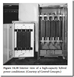
A wide variety of ac power-conditioning systems are available, based on a combination of solid- state technologies. Most incorporate a combination of series and parallel elements to shunt tran- sient energy. One such system is pictured in Figure 14.18.
Active Power-Line Conditioner
The active power-line conditioner (APLC) pro- vides an adaptive solution to many power-quality problems [3]. The major features of APLC include:
• Near-instantaneous voltage regulation
• Source voltage harmonic compensation
• Load current harmonic cancellation
• Distortion power factor correction
The basic concept of the APLC can be expressed in mathematical terms. Figure 14.19 shows a block diagram of the APLC in a simplified power system. As shown, the system has two primary components:
• A component in series with the harmonic sensitive load, which controls the voltage sine wave being supplied by the power system
• A component in parallel with the harmonic sensitive load, which controls the harmonic current going to the load
The voltage that is supplied by the power-distribution system (Vin) contains two components: the fundamental 60 Hz frequency component represented by Vf and the harmonic component of the source voltage represented by Vh. By definition, Vh is any portion of the source voltage that is not of the 60 Hz fundamental frequency. The APLC modifies this incoming voltage by adding two more voltage compo- nents:
• The Vr component, which is the amount of buck or boost required to provide regulation of the output voltage Because the two Vh components cancel, the load receives a regulated sinusoidal voltage at the fundamental frequency with no harmonic components.
The load uses current (IL) in a nonlinear fashion. The harmonic portion of the current Ih is — by definition — everything that is not the fundamental frequency component. The APLC becomes the source of Ih for the load circuit, leaving only the fundamental frequency portion (If ) to be supplied by the power system. Because the harmonic portion of the load current is supplied locally by the APLC, the dis- tortion power factor of the load is near unity.
A digital signal processor (DSP) is used to monitor the input and output parameters of the APLC. The DSP then makes any needed adjustment in the amount of voltage compensation and current injec- tion by modifying the switching characteristics of the insulated-gate bipolar transistors (IGBTs) in the APLC.
A simplified schematic of the APLC power circuitry is given in Figure 14.20. The dc bus (Vdc) is the energy storage device that supplies the power required for voltage compensation and current injection. The parallel filter serves two purposes. First, the IGBTs in this portion of the APLC keep the dc link capacitor charged. Second, it is used as the source for the harmonic currents needed by the load. By using power from the dc link, the series filter compensates for input voltage fluctuations through the buck/ boost transformer.
Series filter Parallel filter
Application Considerations
In a conventional power control system, voltage regulation is performed by using either ferroresonant transformers or tap switching transformers. The fastest response times for either of these solutions is about one half-cycle (8 ms). This response time is the result of the tap-switching transformer’s need for a zero crossing of the waveform to make a change. The use of IGBTs in the APLC allows full power to be switched at any point on the sine wave. Combining these high-speed power transistors with a fast digital signal processor, the voltage can be regulated in less than 1 ms [3]. Furthermore, the input voltage can exhibit up to 10% total harmonic distortion (THD), but output of the APLC to the load will typically see a voltage waveform with less than 1.0% THD [3].
As discussed previously, a switching power supply requires current in a nonlinear fashion. These load currents may have significant harmonic components. The APLC can cancel up to 100% load current THD at full load. The source current being supplied by the power-distribution system will see a purely linear load with no more than 3% current THD [3].


