Low-pressure system
Regardless of the type of high-pressure system, all engines employ similar low- pressure systems.
Lift pumps
A fuel supply, feed, transfer, or lift (the terms are interchangeable) pump sup- plies low-pressure fuel to the suction side of the injector pump or unit injectors. Most lift pumps are driven mechanically, although in recent years, electric drive has become popular. Pressure varies with 50 psi as a ballpark figure.
Stanadyne, Lucas/CAV and Bosch distributor-type injector pumps employ an integral vane-type lift pump as pictured back in Fig. 5-9 and subsequent drawings. The sliding vanes rotate in an eccentric housing with the outlet port on the periphery.
Gear-type lift pumps, similar to lube-oil pumps, develop pressure from the tooth mesh and usually incorporate a spring-loaded pressure-limiting valve.
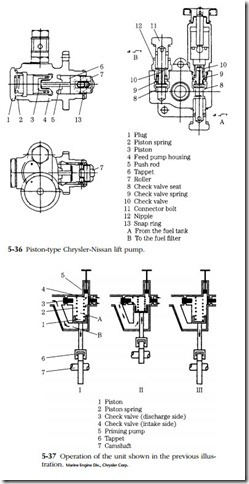
Chrysler-Nissan SD22 and SD33 engines feed through a piston pump driven off the injector pump (Fig. 5-36). The operation of the pump is slightly unorthodox, in that fuel is present on both sides of the piston to eliminate air locks. As the piston retracts, fuel under it is expelled and the inlet check valve opens to admit fuel into the chamber above the piston (Fig. 5-37). As the piston rises, the check valve closes to permit the upper chamber to be pressurized. Fuel under the piston then reverses course to fill the void left by the rising piston. Near tdc the spring-loaded discharge- side valve opens. Spring tension determines pump pressure. The upper chamber can also be pressurized manually to bleed the system.
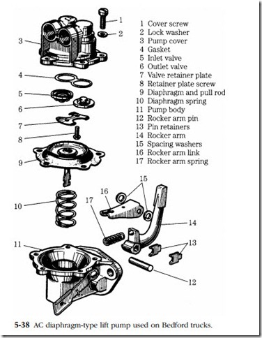
Small engines are often fitted with low-pressure diaphragm pumps such as the AC unit pictured in Fig. 5-38. The pump consists of a spring-loaded diaphragm activated by the engine camshaft. Inlet- and discharge-side check valves are often interchangeable.
Lift-pump service
Loss of pressure is the definitive symptom of pump failure, although it would be helpful if manufacturers provided output volume specifications. Before condemning the pump, check for air leaks as described in the previous chapter. A length of transparent plastic tubing spiced into the pump output line will reveal the presence of air bubbles.
Pump vanes wear in normal service and can stick in their grooves when the fuel turns resinous after an extended shutdown. Gear-type pumps should require no rou- tine maintenance other than inspection during the course of engine overhaul. Wear tends to localize on the pump cover. When pump failure, as from a sheared drive gear, is suspected, it is sometimes possible to establish that the gears turn by inserting a fine wire into the outlet and cranking the engine. The wire should vibrate from contact with the spinning gears.
Check valves are the weak point of reciprocating (piston or diaphragm) pumps. Most check valves can be removed for cleaning or replacement. When this is not pos- sible, a piece of wire inserted into the fuel entry port should unstick the ball, at least temporarily. Diaphragms should be changed periodically and the housing cleaned every 200 hours or so of operation (Fig. 5-39). When installing these pumps, it is good practice to bar the engine over so the pump lever rides on the lower part of the cam.

