Introduction
A wide variety of power-protection technologies are available to solve specific problems at a given facility. Various levels of protection can be provided using the following devices:
• Ferroresonant transformer
• Isolation transformer
• Tap-changing regulator
• Line conditioner
Ferroresonant Transformer
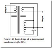
Ferroresonant transformers exhibit unique voltage-regulation characteristics that have proven valuable in a wide variety of applications. Voltage output is fixed by the size of the core, which saturates each half-cycle, and by the turns ratio of the windings. Voltage output is determined at the time of manufacture and cannot be adjusted. The secondary circuit resonance depends upon capacitors, which work with the saturating inductance of the device to keep the resonance active. A single-phase ferroresonant transformer is shown in Figure 14.1.
Load currents tend to demagnetize the core, so output current is automatically limited. A ferroresonant transformer typically cannot deliver more than 125 to 150% of its full-load rated output without going into a current-limiting mode. Such transformers cannot support the normal starting loads of motors without a significant dip in output voltage.
Three-phase versions consisting of single-phase units connected in delta-delta, delta-wye, or wye-wye can be unstable when working into unbalanced loads. Increased stability for three-phase operation can be achieved with zigzag and other special winding configurations.
Shortcomings of the basic ferroresonant transformer have been overcome in advanced designs intended for low-power (2 kVA and below) voltage-regulator applications for DP equipment. Figure 14.2 illustrates one of the more common regulator designs. Two additional windings are included:
• Compensating winding (Wc), which corrects for minor flux changes that occur after saturation has been reached.
• Neutralizing winding (Wn), which cancels out most of the harmonic content of the output voltage. Without some form of harmonic reduction, the basic ferroresonant transformer would be unsuitable for sensitive DP loads.
A unique characteristic of the ferroresonant regulator is its ability to reduce normal-mode impulses. Because the regulating capability of the device is based on driving the secondary winding into saturation, transients and noise bursts are clipped, as illustrated in Figure 14.3.
The typical ferroresonant regulator has a response time of about 25 ms. Because of the tuned circuit at the output, the ferroresonant regulator is sensitive to frequency changes. A 1% frequency change will result (typically) in a 1.5% change in output voltage. Efficiency of the device is about 90% at full rated load, and efficiency declines as the load is reduced. The ferroresonant regulator is sensitive to leading and lagging power factors, and exhibits a relatively high output impedance.
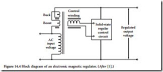
An electronic magnetic regulator uses dc to adjust the output voltage through magnetic saturation of the core. The direct current-fed winding changes the saturation point of the transformer. This action, in turn, controls the ac flux paths through boost or buck coils to raise or lower the output voltage in response to an electronic cir- cuit that monitors the output of the device. A block dia- gram of the magnetic-coupling-controlled voltage regulator is shown in Figure 14.4. Changes in output voltage are smooth, although the typical response time of 5 to 10 cycles is too slow to prevent surge and sag condi- tions from reaching the load.
Figure 14.5 illustrates an electromechanical version of a saturable regulating transformer. Output voltage is controlled by varying the impedance of the saturable reactor winding in series with a step-up autotransformer. Response to sag and surge conditions is 5 to 10 cycles. Such devices usually exhibit high output impedance and are sensitive to lagging load power factor.
Isolation Transformer
Transients as well as noise (RF and low-level spikes) can pass through transformers, not only by way of the magnetic lines of flux between the primary and the secondary, but through resistive and capacitive paths between the windings, as well. There are two basic types of noise signals with
which transformer designers must cope:
• Common-mode noise. Unwanted signals in the form of voltages appearing between the local ground reference and each of the power con- ductors, including neutral and the equipment
• Normal-mode noise. Unwanted signals in the form of voltages appearing in line-to-line and line-to-neutral signals.
Figure 14.5 Autotransformer/saturable reactor volt- age regulator.
Increasing the physical separation of the primary and secondary windings will reduce the resistive and capacitive coupling. However, it also will reduce the inductive coupling and decrease power transfer.
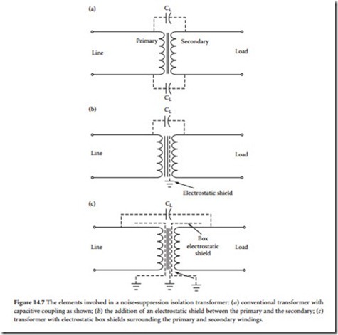
A better solution involves shielding the primary and secondary windings from each other to divert most of the primary noise current to ground. This leaves the inductive coupling basically unchanged. The concept can be carried a step further by placing the primary winding in a shielding box that shunts noise currents to ground and reduces the capacitive coupling between the windings.
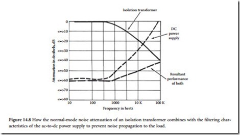
One application of this technology is shown in Figure 14.6, in which transformer noise decoupling is taken a step further by placing the primary and secondary windings in their own wrapped foil box shields. The windings are separated physically as much as possible for the particular power rating and are placed between Faraday shields. This gives the transformer high noise attenuation from the primary to the secondary, and from secondary to the primary. Figure 14.7 illustrates the mechanisms involved. Capacitances between the windings, and between the windings and the frame, are broken into smaller capacitances and shunted to ground, thus minimizing the overall coupling. The interwinding capacitance of a typical transformer using this technique ranges from 0.001 to 0.0005 pF. Common-mode noise attenuation is generally in excess of 100 dB. This high level of attenuation prevents common-mode impulses on the power line from reaching the load. Figure 14.8 illustrates how an isolation transformer combines with the ac-to-dc power supply to prevent normal-mode noise impulses from affecting the load.
A 7.5 kVA noise-suppression isolation transformer is shown in Figure 14.9. High- quality isolation transformers are available in sizes ranging from 125 VA single-phase to 125 kVA (or more) three-phase. Usually, the input winding is tapped at 2.5% intervals to provide the rated output voltage, despite high or low average input voltages. The total tap adjustment range is typically from 5% above nominal to 10% below nominal. For three- phase devices, typical input-voltage nominal ratings are 600, 480, 240, and 208 V line-to- line for 15 kVA and larger.
Tap-Changing Regulator
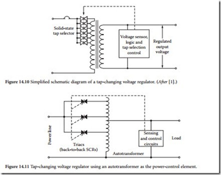
The concept behind a tap-changing regulator is simple: adjust the transformer input voltage to compensate for ac line-voltage variations. A
tap-changing regulator is shown in Figure 14.10. Although simple in concept, the actual implementation of the system can become complex because of the timing waveforms and pulses necessary to control the SCR banks. Because of the rapid response time of SCRs, voltage adjustment can be made on a cycle-by-cycle basis in response to changes in both the utility input and the load. Tap steps are typically 2 to 3%. Such sys- tems create no objectionable switching transients in unity power factor loads. For low-PF loads, however, small but observable transients can be generated in the output voltage at the moment the current is switched. This noise usually has no significant effect on DP loads. Other operating characteristics include:
• Low-internal impedance (similar to an equivalent transformer)
• High efficiency from full load to 25% or less
• Rapid response time (typically one to three cycles) to changes in the input ac voltage or load current
• Low acoustic noise level
An autotransformer version of the tap-changing regulator is shown in Figure 14.11.
Variable Ratio Regulator
Functionally, the variable ratio regulator is a modified version of the tap-changer. Rather than adjusting output voltage in steps, the motor-driven regulator provides a continuously variable range of voltages. The basic concept is shown in Figure 14.12. The system is slow, but generally reliable. It is excellent for keeping DP hardware input voltages within the optimum operating range. Motor-driven regulators usu- ally are able to follow the steady rise and fall of line voltages that typically are experienced on utility company lines. Efficiency is normally good, approaching that of a good transformer. The internal impedance is low, making it possible to handle a sudden increase or decrease in load current without excessive und- ervoltages or overvoltages. Primary disadvantages of the variable ratio regulator are limited current rat- ings, determined by the moving brush assembly, and the need for periodic maintenance.
Variations on the basic design have been marketed, including the system illustrated in Figure 14.13. A motor-driven brush moves across the exposed windings of an autotransformer, causing the series transformer to buck or boost voltage to the load. The correction motor is controlled by a voltage-sensing circuit at the output of the device.
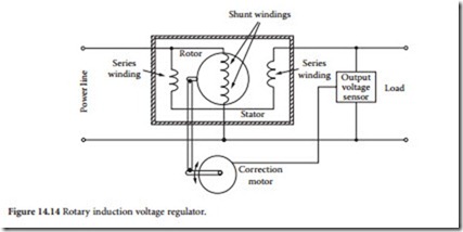
The induction regulator, shown in Figure 14.14, is still another variation on the variable ratio trans- former. Rotation of the rotor in one direction or the other varies the magnetic coupling and raises or low- ers the output voltage. Like the variable ratio transformer, the induction regulator is slow, but it has no brushes and requires little maintenance. The induction regulator has higher inductive reactance and is slightly less efficient than the variable ratio transformer.
Variable Voltage Transformer
Because of their application in voltage control systems, it is worthwhile to discuss the operation of vari- able voltage transformers in greater detail. A number of conventional transformers can have — to a lim- ited degree — their primary/secondary ratio changed through the use of taps located (usually) on the primary windings [2]. To obtain a greater degree of flexibility in changing the ratio between the primary and secondary coils, and thus allow greater secondary voltage changes, a variable voltage transformer is used. The amount of voltage change depends upon the basic construction of the device, which typically divides into one of two categories:
• Brush type
• Induction type
Brush Type
To achieve a variable output voltage, one tap on the transformer secondary is fixed and the other tap is connected to a brush that slides along an uninsulated section of the transformer coil [2]. One way of accomplishing this objective is to have the coil wrapped around a toroidal-shaped core. The voltage ratio relates to the location of the brush as it rides against the coil and depends upon where on the coil the brush is allowed to make contact. Limited ratio variable transformers are available, as well as full-range units that can adjust the output voltage from 0 to about 120% of the incoming line voltage. When the output voltage exceeds the input voltage, it means that there are extra turns on the coil that extend beyond the windings that lie between the incoming power terminals (in effect, the unit becomes a step- up transformer).
Ratings start at less than 1 kVA for a 120 V, single-phase variable transformer. Basic units are wired in parallel or in series to obtain higher power capacity. Two units in parallel have double the current and kVA rating. The individual units are stacked on top of each other, bolted together, and operated from a common shaft that rotates the brushes. Operating in a configuration that combines parallel and series connections, with several units stacked together, this type of variable voltage transformer, at 480 V, can have a rating exceeding 200 kVA. Sometimes, a control mechanism is attached to the rotor that turns the brushes, allowing automatic adjustment of the output voltage.
An important characteristic of this type of transformer relates to brush contact and the amount of current flowing through the carbon brush. A rating based solely on output kVA can cause serious operational problems because, for a given kVA load, the current drawn depends on the output voltage. Because the output voltage is variable, a load of a given kVA value can draw a safe current at 100% voltage, but at 25% voltage, the current required to serve a load of the same kVA value would require four times as much current, which could cause the brush to overheat.
Induction Type
The induction type variable transformer does not use brushes [2]. The usual voltage change for these units is ±10%, but it can be greater. The device is essentially a variable-ratio autotransformer that uses two separate windings, a primary and a secondary. There is a laminated steel stator on which is wound a winding that serves as a secondary coil. This winding is connected in series with the load. The primary coil is connected across the supply line. The shunt winding is wound around a rotor. Construction is sim- ilar to that of a motor except that, in this case, the rotor can only turn 180 mechanical and electrical degrees.
As the primary core is rotated, the amount of primary flux passing through the secondary winding is decreased until the core reaches a position at right angles to the secondary winding. In this position, no primary flux passes through the secondary windings and the induced voltage in the coil is zero. The continued rotation of the core in the same direction again increases the amount of flux passing through the secondary, but it is now in the opposite direction and so reverses the direction of the induced voltage. Thus, the output voltage can be varied by adding or subtracting from it the voltage induced in the secondary winding.
Both single- and three-phase transformers are available. Ratings of these types of transformers vary from 8 kVA, 120 V single-phase to 1500 kVA, 480 V three-phase.
