Position
The potentiometer
The potentiometer can directly measure angular or linear displacements and is the simplest form of position transducer.
Potentiometers have finite resolution which is determined by the wire size or grain size of the track. Since they are mechanical devices, they can also suffer from stiction, backlash and hysteresis. Their failure mode also needs consideration; a track break can cause the output signal to be fully high above the failure point and fully low below it. In closed-loop position control systems this manifests itself as a high-speed dither around the break point.
The synchro and resolver
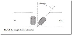
Figure 4.23 shows a transformer whose secondary can be rotated with respect to the primary. At angle θ the output voltage will be given by eqn 4.10,
Vo = K Vi cos θ (4.10)
where K is a constant. The output amplitude is dependent on the angle, and the signal can be in phase (from θ = 270° to 90°) or anti-phase (from θ = 90° to 270°). This principle is the basis of synchros and resolvers.
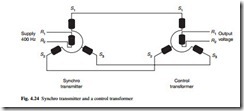
A synchro link consists of a transmitter and a control transformer connected as shown in Fig. 4.24. Although this appears to be a three-phase circuit, it is fed from a single-phase supply, often at 400 Hz. The voltage applied to the transmitter induces in-phase or anti-phase voltages in the windings as described earlier and causes currents
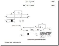
to flow through the stator windings at the control transformer. An ac voltage will be induced in the rotor of the control transformer, if it is not perpendicular to the field. The magnitude of this voltage is related to the angle error and the phase to the direction. The ac output signal must be converted to dc by a phase sensitive rectifier. The Cowan rectifier of Fig. 4.25(a) is commonly used. Another common circuit is the positive/ negative amplifier of Fig. 4.25(b), the electronic polarity switch being driven by the reference supply.
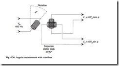
A resolver has two stator coils at right angles and a rotor coil as shown in Fig. 4.26. The voltages induced in the two stator coils are simply
The linear variable differential transformer (LVDT)
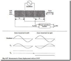
An LVDT is used to measure small displacements, typically less than a few millimetres. It consists of a transformer with two secondary windings and a movable core as shown in Fig. 4.27. At the centre position, the voltages induced in the secondary windings are equal but of opposite phase giving zero output signal. As the core moves away from the centre one induced voltage becomes larger, giving a signal whose amplitude is pro- portional to the displacement and whose phase shows the direction. A dc output signal can be obtained with a phase sensitive rectifier.
The shaft encoder
Shaft encoders give a digital representation of an angular position, and exist in two forms.
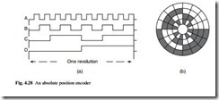
An absolute encoder gives a parallel output signal, typically 12 bits (one part in 4096) per revolution. Binary Coded Decimal (BCD) outputs are also available. A simplified four-bit encoder would therefore operate as shown in Fig. 4.28(a). Most absolute encoders use a coded wheel similar to Fig. 4.28(b) moving in front of a set of photocells. A simple binary coded shaft encoder can give anomalous readings as the outputs change state. There are two solutions to this problem. The first uses an addi- tional track, called an anti-ambiguity track, which is used by the encoder’s internal logic to inhibit changes around transition points. The second solution uses a unit distance code, such as the Gray code which only changes one bit for each step and hence has no ambiguity. The conversion logic from Gray to binary is usually contained within the encoder itself.
Incremental encoders give a pulsed output, each pulse representing a fixed angular distance. These pulses are counted by an external counter to give an indication of the position. Simple encoders can be made by reading the output from a proximity detector in front of a toothed wheel. A single-pulse output train carries no directional information and commercial incremental encoders usually provide two outputs shifted 90° in phase as shown in Fig. 4.29(a). For clockwise rotation, A will lead B as shown in Fig. 4.29(b) and the positive edge of A will occur when B is low. For anti-clockwise
rotation B will lead A. The two-output incremental encoder can thus be used to follow reversals without cumulative error, but can still lose its datum position after a power failure.
The variable capacitance transducer
where ε is the permittivity of the material between the plates, A the area and d the separation. A variation in capacitance can be achieved by sliding in a dielectric to vary ε, or by moving the plates horizontally to change A or by moving the plates apart to change d. Although the change is linear for ε and A, the effect is small.
Laser distance measurement
There are two broad classes of laser distance measurement.
In the triangulation laser shown in Fig. 4.30, a laser beam is used to produce a very bright spot on the target object. This is viewed by an imaging device which can be considered as a linear array of tiny photocells. The position of the spot on the image will vary according to the distance as shown, and the distance is found by simple triangulation trigonometry.
The second type of measurement is used at longer distances. For very long distances, in surveying for example, the time taken for a pulse to reach the target and return is measured. At shorter distances a continuous amplitude modulated laser beam
is sent and the phase shift between transmitted and received signals is used to calculate the distance. The latter method can give ambiguous results, so the two techniques are often combined to give a coarse measurement from time of flight which is fine- tuned by the phase shift.
Proximity switches and photocells
Limit switches are often used to indicate positional state. In mechanical form these devices are bulky, expensive and prone to failure where the environment is hostile.
Proximity switches can be considered to be solid-state limit switches. The most common type is constructed around a coil whose inductance changes in the presence of a metal surface. A simple two-wire AC device acts like a switch, having low imped- ance and capable of passing several hundred milliamperes when covered by metal, and a high impedance with a typical leakage of 1 mA when uncovered. Sensing distances up to 20 mm are feasible, but 5 mm to 10 mm is more common. DC-powered switches use three wires, two for the supply and one for the output. DC sensors use an internal high frequency oscillator to detect the inductance change which gives a much faster response. Operation at several kilohertz is easily achieved.
Inductive detectors only work with metal targets. Capacitive proximity detectors work on the change in capacitance caused by the target and accordingly work with wood, plastic, paper and other common materials. Their one disadvantage is that they need adjustable sensitivity to cope with different applications.
Ultrasonic sensors can also be used, operating on the same principle as the level sensor described in section 4.6.3. Ultrasonic proximity detectors often have adjustable near and far limits so that a sensing window can be set.
Photocells (or PECs) are another possible solution. The presence of an object can be detected either by the breaking of a light beam between a light source and a PEC or by reflecting a light beam from the object which is detected by the PEC. In the second approach (called a retro-reflective PEC) light is seen for an object present. It is usual to use a modulated light source to minimize the effects of change in ambient light and to prevent interaction between adjacent PECs.
