WAVE POWER
The waves found in seas and oceans are created when the sea absorbs energy from the wind. The stronger the wind and the longer the reach of sea over which it has to blow, the greater the amount of energy that is absorbed. The rotation of Earth means that the best wind regimes are generally found on western shore- lines exposed to the wide ocean and the strongest winds are between 30o and 60o degrees of latitude. Good sites can be found along the western coasts of Europe, North and South America, Africa, Indonesia, Malaysia, New Zealand, and Australia.
The energy contained within waves is manifested as an oscillatory motion of the sea surface. Over very long reaches this can assume a regular frequency, as characterized by the swell found on the oceans, but often and particularly near the coast it will become a superposition of a number of different frequen- cies. Whatever its precise nature, the motion from the point of view of energy capture is an oscillation of the water surface relative to a fixed point on land or on the seabed. It is this motion that must be exploited in a wave energy con- verter. (Some converters also exploit the relative motion of two adjacent points on the surface.)
Wave energy is characterized by the amount of energy contained within a 1 m wave front as it arrives at the point of capture. Far out to sea, waves can contain as much as 100 kW/m, and this energy is retained while the waves remain in deep water but the energy content generally falls as the waves approach the coast. At a depth of 20 m, the energy content will typically have fallen by two-thirds.
Average annual wave energy levels along the coast of western Europe are 48–70 kW/m, and in the Americas they can range from 13–102 kW/m with the highest energy levels generally found in the more northerly or southerly parts of those continents. Energy content varies seasonally too, with more energy gen- erally found in winter than in summer.
The possibility of harnessing waves as a power source was first explored dur- ing the 19th century, initially as a means of ship propulsion but later as a land- based means of energy capture. The earliest actual wave power machines were built in California between 1890 and 1910 when several “wave motors” were constructed though most were unsuccessful. After this, interest died until the 1970s when projects were launched in the United Kingdom, Japan, and Norway. None of these schemes appeared to be economically viable but interest grew again during the 1990s, and during the first decade of the 21st century, scores of new projects were launched using a wide range of differing technologies. Most are at an early pilot or demonstration stage but interest remains high.
Wave Power Technology
The quest to exploit the oscillatory motion of waves has given birth to a bewildering range of mechanical devices designed to convert that motion into electricity. Some of these are shore based, and some will only operate far out to sea. The principles upon which they operate vary widely too and there is no easy way to classify them.
Shoreline devices include oscillating water column converters and a range of overtopping devices. Oscillating flap converters are usually built close to the shore too. Offshore devices include floats, point absorbers, and wave pumps, all of which need to be tethered to the seabed to operate. Another series of offshore devices, with names such as snake and duck, use the relative motion of a series of floating elements, one against the other as a source of energy. There are also piezoelectric devices that generate electrical energy through the bending of a special material. These can be both shoreline and offshore energy converters.
Shore and Near-shore Wave Converters
Oscillating Water Columns
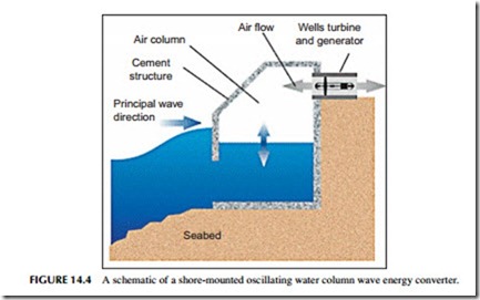
One of the simplest and most common methods of capturing energy from wave motion is with an oscillating water column (OWC) device (Figure 14.4). This comprises a tube or chamber that has a lower aperture below sea level and the opposite end above sea level, open to the air. The simplest way of envisaging an OWC is to think of a tube with one end immersed in the sea. As waves pass across the tube, the water level within it will rise and fall, alternately forc- ing air from the top of the tube or sucking it in. This motion of air can be harnessed to turn a type of wind turbine, generating electricity.
Since the movement of air is cyclic, alternately traveling in and out of the tube as waves pass, a conventional turbine would rotate first one way and then the other, and so it would be unable to generate with a conventional generator. There are two solutions to this. The first is to employ a system of valves and two turbines, one that rotates as air is forced from the tube and the other that rotates when air is drawn in. A more elegant solution is to use a turbine that can rotate in
the same sense whichever direction the air flows. The most commonly used of these is a Wells turbine.
OWC devices can either be built on the shore or in shallow near-shore waters. They usually comprise some form of concrete structure anchored to the seabed or shoreline with seawater admitted to an aperture in the part beneath the water level. The device must be large enough so that its lower aperture is always submerged whatever the state of the tide. Otherwise, it will not be able to generate throughout the tidal cycle.
The energy source driving an OWC is variable and conversion into electrical power results in a highly variable output. If the turbine is designed with a significant moment of inertia this can help smooth the output but it will remain highly variable without further smoothing.
A variety of pilot-scale OWC energy converters have been built including a 500 kW unit called the Limpet that was built on the Scottish isle of Islay by a company called Wavegen in 2000. Since then a 4 MW has been proposed involving 30–40 Wells turbines. This project was to be built at Siadar Bay, on the island of Lewis in Scotland, but the project was canceled in 2012.
Overtopping Devices and Tapered Channels
Another simple method for extracting energy from waves is to consider them simply as a variable head of water. If some of the water from the crests of waves can be captured it can be used to create a head of water that rises above the sur- rounding sea level, and this can then be exploited to drive a hydroturbine and generate power with the water from within the device running back to the sea.
Creating a head of this sort can be achieved in a number of ways. One of the early attempts, called a Tapchannel, funneled waves into a rising and narrowing channel where the kinetic energy of the waves was used to force water to over- flow the sides of the channel into a small reservoir built on the seashore. The water was then allowed to run back to the sea through a turbine.
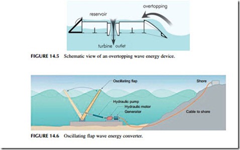
Another approach is to build an offshore reservoir in shallow waters with gently sloping sides so that the energy of the waves as they drive toward the shore forces water to flow over the sides of the reservoir (Figure 14.5). As with the Tapchannel, the water collected in this way is then allowed to flow back to the sea through a turbine.
The head of water created in this way is relatively small and a low-head tur- bine is required to extract energy from it efficiently. Kaplan turbines have been used successfully in some pilot schemes of this type.
One of the overtopping devices currently being developed is the Wave Dragon. This was originally developed by a Danish company of the same name. Wave Dragon Wales won funding in 2011 to build a 7 MW prototype off the Welsh coast of Pembrokeshire. However, in 2013 the energy converter was still not constructed.
Oscillating Flaps
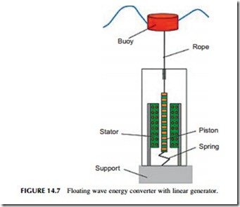
A third common near-shore wave energy converter is the oscillating flap device, sometimes also called an inverted pendulum converter (Figure 14.6). The basic principle behind this type of converter is to devise a buoyant flap, the bottom of
which is hinged and attached to a foundation anchored to the seabed. The body of the flap then rises under water above the hinge. As waves move across the site of the device, they cause the flap to oscillate backwards and forwards and this oscillatory motion is converted into electrical power.
A similar principle can be exploited using a foundation structure that rises close to the surface of the sea. In this case the structure supports a weighted flap that is hinged from the top and falls down into the sea. Again, as waves cross the site of the device they cause the flap to move backwards and forwards.
Energy conversion with such devices is often carried out by using the oscillating motion to power a pump that drives a fluid, often seawater, under pressure through a pipe to the shore. A high-pressure flow of water of this type can then be converted into electricity using a Pelton turbine, normally used for high-head hydropower plants. With a system of this type, several wave energy converters can be used to provide pressurized water to a single turbine. In addition, water can be stored under hydrostatic pressure in an accumulator, allowing this type of wave energy device to store energy and smooth its output, providing a more valuable source of power for the grid.
One oscillating flap device that has been under development is the Waveroller, from Finnish company AW-Energy. The company deployed a pilot scheme off the Portuguese coast in 2012 comprising three 100 kW Waveroller oscillating units. The company is hoping to be able to use the pilot to develop a 500 kW commercial unit. A second oscillating flap device called the Oyster has been developed by U.K. company Aquamarine Power. A single 800 kW dem- onstration unit was installed at the European Marine Energy Centre, Orkney, in 2012. This uses the pump principle to bring pressurized water ashore to drive a hydroturbine.
Offshore Devices
Buoyancy-based Devices
One of the principal categories of offshore wave energy converters is based on a floating device such as a buoy that is tethered to the seabed. While such devices can operate close to shore, since the energy contained in waves is greater farther offshore they are better deployed in deep water.
A buoyancy device will be attached to an anchor that is fixed to the seabed. The device itself will then float to the surface, or it might be held just below the surface. In either case, the passage of waves will create an oscillating force act- ing on the buoy as passing waves pull it toward the surface and away from the seabed. This force is then used to generate electricity.
The force can be converted into a useful form of energy in a number of ways. One method involves installing a flexible hose as part of the tethering anchor. This hose is alternately stretched and released as waves pass, applying a pres- sure cycle to the tether. The motion causes the tube to contract and expand, and this can be used to generate a hydrostatic pressure that can be converted into electric power. Another, similar, approach is to use a piston pump fitted to the tether or buoy. The movement of the buoy up and down drives a piston in and out of a cylinder integrated into the device and this can be used to generate hydrostatic pressure too.
The main alternative to using the motion to pump water is a linear generator. This is a device that can produce electricity from linear rather than rotary motion (Figure 14.7). If a generator of this type is fitted into the tether of a buoy, the up and down motion as the buoy is lifted and dropped by waves can then be turned directly into electrical power.
Pontoons, Snakes, and Ducks
The second principal category of offshore wave energy converters comprises a disparate group of machines that have one thing in common. Each is made up of a number of floating sections that are joined end to end through a hydraulic link- age. When one of these devices is taken out to sea the sections will move relative to each other and this relative motion is used to extract power.
One of the earliest wave power devices, called the Salter’s Duck after its inventor, Stephen Salter, was a converter of this type. Devised in the 1970s, it comprised a large anchored section to which was fitted a lighter hinged “beak.” When moored offshore, wave motion caused the beak to oscillate up and down and this motion was exploited to provide power.
Some devices of this sort are made up of two or more elements of the same size. The relative motion of these as they jostle under the influence of the waves
at sea then allows power to be extracted. Others are designed with one large, relatively immobile element and another that is tuned to respond to the motion of the waves. This latter group is often called point absorbers and they may be tethered to the sea bed, like buoyancy devices, above. Tuning a device in this way will nor- mally mean that it only responds to a band of wave frequencies and is unaffected by others outside this band. Whatever the design, however, the principle is the same: one part of the device moving relative to the other, as shown in Figure 14.8.
As with other offshore devices, energy can be extracted by using the motion to pump water, by generating hydrostatic pressure that can be used to produce electricity, or by using some sort of linear generator. An example of this latter approach is the Archimedes Wave Swing, an underwater tethered buoy that was originally developed in The Netherlands but is now owned by U.K. company AWS Ocean Energy. A 2 MW prototype was tested off the Portuguese coast in 2005 where it achieved an output of 1 MW. More recently, AWS Ocean Energy has been awarded £3.9 m to build its latest prototype.
Another tethered buoy is the Powerbuoy being developed by U.S. company Ocean Power Technologies. Like the Archimedes Wave Swing this is a point absorber tuned to extract energy from ocean waves. The company has tested several prototypes but is currently developing what is proposed to be its first commercial deployment off the coast of Oregon. This will initially involve one 150 kW unit followed by 10 grid-connected units providing a total of
1.5 MW. Following this, the company plans a 50 MW installation. Factory testing of the first unit was completed in mid-2012.
Yet another tethered buoy is the Aquabuoy, in this case a floating device, which has also been tested off the coast of Oregon. There were plans for a 2 MW grid-connected power plant selling power to a U.S. utility but there have been no recent reports of progress.
Of the second type of offshore floating devices, the main example today is the
Pelamis developed by Pelamis Wave Power. This comprises a series of buoyant cylindrical sections linked through hydraulic joints. Movement of the sections pumps oil that is used to drive a generator. A 750 kW prototype comprising three 250 kW units was deployed off the coast of Scotland in 2005, and in 2008 three units were installed off the Portuguese coast but had to be brought back ashore later that year. Since then there appear to have been no further units installed.
Piezoelectric Devices
Piezoelectric materials produce an electric voltage when they are placed under stress. This may be a result of bending, stretching, or a variety of other means including when they are subjected to vibrations. Any and all of these means of generating electricity could potentially be exploited in a wave energy device.
One idea that has been put forward involves piezoelectric “seaweed.” Wafers of a piezoelectric material are anchored to the seabed so that the wash of waves across them causes them to bend backwards and forwards, generating electricity. A second involves the stretching of a piezoelectric material that could, in principle, be used to generate power from a tethered buoy if the generator was mounted into the tether. However, while there are a wealth of possible ways such materials could be used, no wave converter using them has yet been built.


