Introduction
Insulating oils, fluids, and gases are used as dielectrics in the electrical equipment and apparatus. The liquids used in the transformers are mineral oil and synthetic fluids, such as askarel, silicone, RTemp, Wecosal, Alpha 1, and GE R113. (The synthetic fluids such as askarel, silicone, RTemp, etc. have a fire point of not less than 300°C and are classified as less flammable insulat- ing fluids by the National Electric Code, NEC.) Mineral oil is also used as a dielectric in circuit breakers, reclosers, interrupters, and the like. The most common insulating gas used in circuit breakers and completely enclosed substations is sulfur hexafluoride (SF6). This chapter covers electrical, chemi- cal, and visual tests which are normally conducted for the maintenance of transformer oils and fluids. Also, this chapter includes a discussion on the inspection, handling, and reconditioning of insulating oil, fluids, and gases used in electrical equipment.
The ability of insulating oils, fluids, and gases to serve as effective dielec- tric and coolant is adversely affected by their deterioration. The deterioration of insulating oil, fluids, and gases is due to contamination, overheating, elec- trical stress, and oxidation. Moisture is the most common contaminant which adversely affects the insulating properties of these liquids and gases. High temperatures from increased load and/or environmental conditions acceler- ate the deterioration process. To assure continuity of service, safety, and maintenance, a condition monitoring program, consisting of electrical and chemical testing, is necessary for these dielectrics.
Insulating Oil
Hydrocarbon (mineral oil #10) oil is used as an insulating fluid in transformers and circuit breakers because of its high dielectric strength and chemical stability. To properly maintain the transformer oil free of contaminants, regular inspection of the transformer and purification of the oil is needed. A brief discussion on the deterioration of the insulating oil is undertaken for maintenance purposes.
Moisture contamination is the most common cause of deterioration in the insulating quality of oil. This contamination can be readily corrected by purification. A slow but more serious deterioration, the formation of acids and sludge, is caused by oxidation. Thus, the exclusion of oxygen is of prime importance. In open-breather transformers, the oxygen supply is virtually unlimited and oxidative deterioration is faster than sealed trans- formers. Atmospheric oxygen and oxygen contained in water are the sources available for the oxidation of insulating oils. When water is present in insulating oils, oxidation of the oil will take place. Therefore, leaking gaskets and seals constitute a very real hazard since a water leak is, in effect, an oxygen leak. The rate of oxidation also depends on the temperature of the oil; the higher the temperature is, the faster the oxidative breakdown. An increase in temperature of 10°C (50°F) generally doubles the rate of oxidation. The fact points to the importance of avoiding overloading of transformers, especially in the summertime. Oxidation results in the for- mation of acids in the insulating oil and the formation of sludge at a more advance state of oxidation.
Moisture in Oil
Water can be present in oil in a dissolved form, as tiny droplets mixed with the oil (emulsion), or in a free state at the bottom of the container holding the oil. Demulsification occurs when the tiny droplets unite to form larger drops, which sink to the bottom and form a pool of free water. Emulsified water typically requires vacuum dehydration, as the emulsification cannot typi- cally be broken by filtration or by excellerated gravity (centrifuge). Water in the free state may be readily removed by filtering or centrifugal treatment. However, dissolved water is not removed by centrifugal treatment; the filtra- tion process can partially remove dissolved water if the filter papers are thor- oughly dried before filtration, but the efficiency of the filtration process depends upon oil temperature and filtration media.
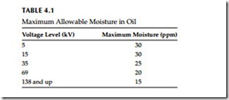
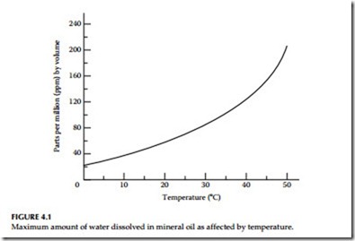
The effect of moisture on the insulating properties of oil depends upon the form in which the moisture exists. A very small amount of emulsified water has a marked influence in reducing dielectric strength of oil. Free moisture in oil usually shows up above 50 to 60 ppm depending upon temperature. Accepted levels of water in oil are shown in Table 4.1. The amount of moisture that can be dissolved in oil increases rapidly as the oil temperature increases, as shown in Figure 4.1. Therefore, an insulating oil purified at too high a temperature may lose a large percentage of its dielectric strength on cooling, because the dissolved moisture is then changed to an emulsion, unless vacuum dehydration is used as the puri- fication process.
In transformers, sludge sticks to the surface through which heat should be dissipated; the sludge forms a blanket barrier to the flow of heat from the oil to the coolant and from the core and coils to the cool oil. If allowed to con- tinue long enough, the sludge may even block off the flow of oil through the cooling ducts. As a result, the transformer insulation gets too hot and is dam- aged, particularly between turns of the windings. Deterioration of the turn insulation may eventually lead to short circuits between turns and the break- down of the transformer. When oxidation progresses to the point where sludge is being precipitated, the first step should be to remove the sludge from the transformer by a high-pressure stream of oil or hot oil circulation to dissolve the sludge, or to either replace the sludged oil or treat it with acti- vated clay to remove the acid. Under favorable conditions, complete treatment of the oil is less costly than replacing it with new oil.
Absorption of Moisture by Insulating Materials
Solid insulation (paper insulation) in transformers is very porous and thirstily absorbs water. Some of the water that is dissolved in the oil is absorbed from the oil by the cellouse (paper) winding insulation. As more water is dissolved in the oil, more water is absorbed by the insulation of the transformer wind- ings. Once absorbed, it is difficult to remove. The most effective method for drying out the insulation in transformers is with heat and vacuum. Sometimes a vacuum cannot be applied in the field; then the transformer insulation must be dried by circulation of hot, dry oil. This oil should then be cooled and dried. Since the dielectric strength of insulation is reduced by absorption of moisture, it is important that the insulation not be allowed to absorb it in the first place.
Absorption of Nitrogen by Oil
Special precaution should be taken in operating transformers with nitrogen over the oil to avoid bubbling of the oil due to release of dissolved nitrogen when the pressure drops. Experience has shown that the automatic gas- pressure regulating system should be adjusted to limit the nitrogen pressure range from 1/2 to 3 psi (lb/in.2) gauge to avoid formation of these bubbles and subsequent troubles due to corona deterioration.
4.2.2 Insulating Oil Testing
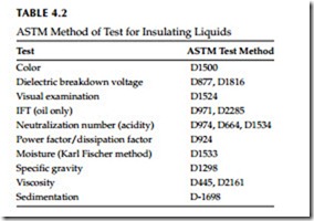
Transformer oil reacts with oxygen to form organic acids, esters, and phenolic compounds which ultimately leads to sludging of the transformer. The rate of this phenomena increases with an increased exposure to air and temperature. Also it should be noted that oxygen is more soluble in oil than found in air. Not only will the sludge adversely affect the dielectric properties of the oil, but it will also interfere with dissipation of heat within the transformer. The pur- pose of these tests are to chart the gradual deterioration and take preventative measures before insulating oil reaches a point where failure of the transformer is inevitable. The routine tests and sampling procedures that are conducted on insulating oil are shown in Table 4.2, and are discussed in text of this chapter.
4.2.2.1 Dielectric Breakdown Voltage Test (Cup Tests)
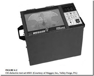
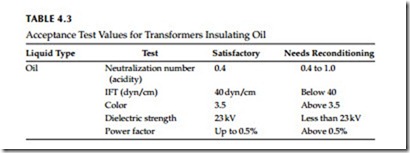
This is an AC overvoltage test applied to the insulating liquids to detect their breakdown strength. A typical test set is shown in Figure 4.2. The American Society for Testing and Materials (ASTM) has established test standards for these liquids, which are listed in Table 4.2. The dielectric test simply consists of placing a liquid sample from the transformer or (circuit breaker) in a cup containing two electrodes of specified gap. High voltage is then applied to the sample. The test is repeated for a least five different samples to determine the average dielectric strength. The minimum accepted values for the various liquids are listed in Table 4.3.
Two different electrodes are used in these tests, one for mineral-based oils and the other for mineral-based oils and synthetic liquids. The Verband Dentschev Elektrotechniker (VDE) cup is used for mineral-based oils; it has
a gap of 0.04 to 0.08 in. (1–2 mm) with a rate of voltage rise of 500 V/s. The disk cup is used for mineral-based oils and synthetic liquids such as askarel, silicone, and others. It has a gap of 0.1 in. with rate of rise of 3000 V/s. The step-by-step procedures for conducting these tests are described next.
Dielectric test ASTM D-877 (disk electrodes): Portable oil dielectric testers are usually used for making dielectric tests on oils in the field. Units with a vari- able high voltage of 40 kV or greater between the electrodes and which have Bakelite test cups are considered satisfactory. Instructions and procedures are as follows:
The electrodes and the test cup should be wiped clean with dry, calen- dered tissue paper or with a clean, dry chamois. The spacing of the elec- trodes should be checked with a standard round gauge having a diameter of 0.1 in. (2.5 mm) or with flat steel go and no-go gauges having thicknesses of 0.0995 and 0.1005 in., respectively; the electrodes should be locked in posi- tion. It is important to avoid touching the electrodes or the cleaned gauge with the fingers or with portions of the tissue paper or chamois that have been in contact with the hands.
The electrodes and test cup should be rinsed with dry, lead-free gasoline or other suitable solvent until they are entirely clean. To avoid any possible contamination, care should be taken to avoid touching the electrodes or the inside of the cup after cleaning.
After a thorough cleaning, the test cup is filled with a sample of the cleaning fluid; voltage is applied and uniformly increased at a rate of approximately 3 kV/s (rms value) until breakdown occurs. If the breakdown is not less than the established value of the oil being tested, the test cup should be consid- ered in suitable condition for testing. If a lower value is obtained, the cup should again be thoroughly cleaned and the test repeated. A cleaning fluid whose breakdown is not less than the established value of the oil being tested must be used.
At the beginning of each test, the electrodes should be examined for pitting and carbon accumulation and the electrode spacing should be checked. The test cup should be thoroughly cleaned and tested as described previously. It should then be flushed with a portion of the sample to be tested before it is filled for the test.
If the test of a sample is below the breakdown value being used by the oper- ator as a minimum satisfactory value, the cup should be cleaned and prepared before testing the next sample. Evaporation of the cleaning fluid from the elec- trodes may chill them sufficiently to cause moisture to condense on their sur- faces. For this reason, after the final rinsing with cleaning fluid, the cup must immediately be flushed with the oil to be tested and then filled for the test.
The dielectric strength of liquid dielectrics may be markedly altered by the migration of impurities through the liquid. To obtain representative test specimens, the sample container should be gently tilted or inverted and the oil swirled several times before each filling of the test cup, in such a way that any impurities present will be thoroughly mixed with the liquid dielectric.
Too rapid agitation is undesirable, since it introduces an excessive amount of air into the liquid. Immediately after agitating, the test cup should be filled with oil to a height of not less than 20 mm (0.787 in.) above the top of the electrodes. To prevent the escape of entrapped air, the container should be gently rocked a few times and the oil allowed to stand in the cup for 3 min before voltage is applied.
The temperature of the sample when tested should be the same as that of the room, but not less than 20°C (68°F). Testing of oil at a lower than the room temperature is likely to give variable results, which may be misleading.
Voltage should be applied and increased at a uniform rate of 3 kV/s from zero until breakdown occurs, as indicated by a continuous discharge across the gap. Occasional momentary discharges that do not result in a permanent arc may occur; they should be disregarded.
Referee testing: When it is desired to determine the dielectric breakdown voltage of a new liquid for referee purposes, one breakdown should be made on each of five successive fillings of the test cup. If the five values meet the minimum dielectric values, the average should be reported as the dielectric breakdown voltage of the sample. If they do not meet the minimum dielec- tric values, one breakdown on each of five additional cup fillings should be made and the average of the 10 breakdowns reported as the dielectric break- down voltage of the sample. No breakdown should be discarded.
Routine testing: When it is desired to determine the dielectric breakdown voltage of a liquid on a routine basis, one breakdown may be made on each of two fillings of the test cup. If no value is below the specified acceptance value, the oil may be considered satisfactory, and no further tests are required. If either of the values is less than the specified value, a breakdown should be made on each of three additional cup fillings, and the test results analyzed.
Alternative method: When it is desired to determine the dielectric breakdown voltage of a liquid on a routine basis, five breakdowns may be made on one cup filling with 1 min intervals between breakdowns. The average of the five break- downs should be considered the dielectric breakdown voltage of the sample, provided the breakdown values meet the criterion for statistical consistency. If the breakdown voltages do not meet this criterion, the contents of the cup should be discarded, the sample container again gently inverted and swirled, the cup again filled, and five breakdowns made on this second cup filling. The average of the 10 breakdowns should be considered as the dielectric break- down voltage of the sample. No breakdown should be discarded.
Criterion for statistical consistency: Compute the range of the five breakdowns (maximum breakdown voltage minus minimum breakdown voltage), and multiply this range by three. If the value obtained is greater than the next to the lowest breakdown voltage, it is probable that the standard deviation of the five breakdowns is excessive, and therefore the probable error of their average is also excessive.
Dielectric test ASTM D-1816 (VDE electrode): The present ASTM D-877 gap consists of 1 in. diameter disk, square-edged electrodes spaced at 0.1 in. The use of this test gap results in a uniform electrostatic field at the center line of the test disks and a highly nonuniform field at the edges of the disk. To attain uniform field strength at all points, spherical electrodes would have to be used. Between these extremes of a highly distorted field and an ideal uni- form field, a third gap configuration, designated as VDE, has been used. The VDE gap specifications call for a sector diameter of 36 mm and a 25 mm radius of curvature for the spherically capped electrodes. A gap of about 0.08 in. between electrodes has been found to give about the same breakdown volt- age relationships in the 25–30 kV range as the ASTM D-877 configuration. Tests have shown the following:
VDE configuration depicts more accurately the average electric strength and scatter of the oil as the transformer sees it VDE gap is relatively sensitive to oil quality ASTM D-877 is less sensitive Point electrodes are almost completely insensitive to oil quality The VDE cell, in which a quart of oil is tested between VDE electrodes, while being mildly circulated, realistically measures changes in oil strength, which determine the electrical strength of typical transformer construction. This test method (ASTM D-1816) is similar to ASTM D-877. The procedure for the VDE (ASTM D-1816) test is the same as for the disk electrodes (ASTM D-877).
Acidity Test
New transformer liquids contain practically no acids if properly refined. The acidity test measures the content of acids formed by oxidation. The acids are directly responsible for sludge formation. These acids precipitate out, as their concentration increases, and become sludge. They also react with metals to form another form of sludge in the transformer. The ASTM D974 and D664 are laboratory tests whereas D1534 is a field test which determines the approximate total acid value of the oil.
The acid number of the neutralization number is the milligrams (mg) of potassium hydroxide (KOH) required to neutralize the acid contained in 1 g of transformer liquid. Test data indicate that the acidity is proportional to the amount of oxygen absorbed by the liquid. Therefore, different trans- formers would take different periods of time before sledge would begin to appear. Transformers with free air access would have formation of sludge before transformers with conservators; and transformers with conservators would have sludge before transformers bolted tight; and transformers bolted tight would have sludge before transformers with nitrogen over oil. Refer to Table 4.3 for acceptable values of the naturalization number for the transformer oil.
The following is a brief description of the ASTM D1534 (Gervin) method for the neutralization number test: Pour the oil sample into a glass cylinder furnished with the Gervin test kit. Single doses of KOH are furnished in sealed ampules with the dosage indicated on the ampules. For example, if the oil level in the glass cylinder is up to mark 10, then number 3 ampules equals 0.3 mg of KOH gram of oil; a number 6 ampules equals 0.6 mg of KOH, and a number 15 equals 1.5 mg of KOH.
The pint bottles contain neutral solution to be put in the measured sample before adding the KOH. This solution washes the oil and the KOH can then act on the acids more readily. The neutral solution contains a color-changing indicator. If any KOH is left after the acids are neutralized, the indicator is pink. But if the KOH is all used up, the indicator is colorless like water.
Interfacial Tension (IFT)
It should be recognized that the acidity test alone determines conditions under which sludge may form, but does not necessarily indicate that actual sludging conditions exist. The IFT test is employed as an indication of the sludging char- acteristics of power transformer insulating liquid. It is a test of IFT of water against liquid, which is different from surface tension in that the surface of the water is in contact with liquid instead of air. The attraction between the water molecules at the interface is influenced by the presence of polar molecules in the liquid in such a way that the presence of more polar compounds causes lower IFT. The polar compounds are sludge particles or their predecessors.
The test measures the concentration of polar molecules in suspension and in solution in the liquids and thus gives an accurate measurement of dissolved sludge components in the liquid long before any sludge is precipitated. It has been established that an IFT of less than 15 dyn/cm almost invariably shows sludging. An IFT of 15–22 dyn/cm is generally indicative of no sludging. For maintenance purposes IFT values are shown in Table 4.3 for transformer oil.
Color Test
This test consists of transmitting light through oil samples and comparing the color observed with a standard color chart. The color chart ranges from
0.5 to 8, with the color number 1 used for new oil. Color test values are listed in Table 4.3.
Power Factor Test
The power factor of an insulating liquid is the cosine of the phase angle between applied sinusoidal voltage and resulting current. The power factor indicates the dielectric loss of the liquid and thus its dielectric heating. The power factor test is widely used as an acceptance and preventive mainte- nance test for insulating liquid. Liquid power factor testing in the field is usually done with portable, direct-reading power factor measuring test
equipment, which is available from several companies, who provide this service. Power factor tests on oil and transformer liquids are commonly made with ASTM D-924 test cell.
Good new oil has a power factor of 0.05% or less at 20°C. Higher power factors indicate deterioration and/or contamination with moisture, carbon or other conducting matter, varnish, glyptal, sodium soaps asphalt compounds, or deterioration products. Carbon or asphalt in oil can cause discoloration. Carbon in oil will not necessarily increase the power factor of the oil unless moisture is also present. It is suggested that the following serve as guides for grading oil by power factor tests.
Oil having a power factor of less than 0.5% at 20°C is usually consid- ered satisfactory for service.
Oil having a power factor between 0.5% and 2% at 20°C should be con- sidered as being in doubtful condition and at least some type of investigation should be made.
Oil having a power factor of over 2% at 20°C should be investigated and should be reconditioned or replaced.
The preceding guides may be elaborated on by saying that good new oil has a power factor of approximately 0.05% or less at 20°C and that the power factor can gradually increase in service to a value as high as 0.5% at 20°C without, in most cases, indicating deterioration. When the power factor exceeds 0.5%, an investigation is indicated. The question of what decision to make regarding disposition of the oil depends on what is causing the high power factor. Dielectric strength tests should be made to determine the pres- ence of moisture. The necessity for further tests will depend to a large extent on the magnitude of the power factors, the importance of the apparatus in which the oil is used, its rating, and the quantity of oil involved.
Specific Gravity
Specific gravity of oil is defined as the ratio of the mass of a given volume of oil to the mass of an equal volume of oil of water at a specified temperature. This test is conducted by floating a hydrometer in oil and taking the reading at the meniscus. For oil free of contaminants, such as water, askarel, or silicone, the reading should be less than 0.84.
Water Content Test (Karl Fisher Method)
This test is based on the reduction of iodine according to the traditional Karl Fisher reaction. Three methods are used to conduct this test. Methods A and C utilize iodine present in a titration solution while Method B elec- trically generates the iodine in the equipment. Moisture content of 69 kV and higher voltage transformers should be measured regularly and lower voltage transformers on indication of flow dielectric strength of the oil.
Combustible Gas Analysis of Insulating Oil
Introduction
An oil-filled transformer insulation system consists of insulating oil and cellulose (paper) materials. Under normal use, transformer insulation dete- riorates and generates certain combustible and noncombustible gases. This effect becomes more pronounced when the transformer insulation is exposed to higher temperatures. When cellulose insulation (i.e., winding insulation) is overheated to temperatures as low as 140°C, carbon monoxide (CO), carbon dioxide (CO2), and some hydrogen (H) or methane (CH4) are liberated. The rate at which these gases are liberated depends exponentially on the tem- perature and directly on the volume of the insulation at that temperature. When insulating oil is overheated to temperatures up to 500°C, ethylene (C2H4), ethane (C2H6), and methane (CH4) are liberated. When oil is heated to extreme temperatures, such as an electrical arc, hydrogen (H) and acetylene (C2H4) are liberated in addition to the above mentioned gases.
The main cause of gas formation in a transformer is due to the heating of paper and oil insulation and electrical problems inside the transformer tank. The electrical problems can be classified as low-energy phenomena, such as corona, or high-energy phenomena, such as an electrical arc. The interpreta- tion of the test data in terms of the specific cause (or causes) is based on the type of gas (or gases) and the quantity of that gas found in the transformer. The detection, analysis, and identification of these gases can be very helpful in determining the condition of the transformer. Establishing a baseline data as a reference point for new transformers and then comparing with future routine maintenance test results is a key element in the application of this test method. However, monitoring or assessing the condition of a transformer using this method can start at anytime even if the reference data is not avail- able. There are two methods for detecting these gases: (1) total combustible gas analysis (TCGA), and (2) dissolved gas analysis (DGA).
TCG
TCG can be determined in the field or analyzed in the laboratory from a sample of gas drawn from the gas space above the oil. The method is appli- cable to power transformers with a nitrogen blanket or conservator system. To facilitate the combustible gas testing, all transformers using a nitrogen blanket should have a gas sampling line installed from the upper portion of the tank to a ground-level sampling valve. Transformers having a conservator tank should have a gas sampling line installed from its gas accumulation relay to a ground-level sampling valve. The equipment used for measuring TCG is basically a Wheatstone bridge circuit. A combination of air and com- bustible gas sample is passed over a resistor where catalytic burning takes place on the resistor, which causes a proportional change in resistance. Based on the change in resistance of the resistor, the TCG is measured in percent.
DGA
The DGA is basically a laboratory test using an oil sample taken from a trans- former. The oil sample is subjected to a vacuum to remove the combustible gases. These gases are then passed through a gas chromatograph and each gas is then extracted and analyzed for type and quantity. The quantity of each gas is given in part per million (ppm) or percent of the total gas present. The analysis of each gas present provides a useful tool in determining the condition of the transformer. The interpretation of the analysis has not yet been perfected to an exact science and is therefore subject to interpretation.
Comparing the Two Methods
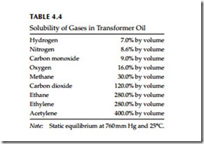
The total fault gas analysis (TCGA) is probably the most widely used in the field. Its major advantages are that it is quick and can be used in the field or may be used to continuously monitor the transformer. Its disadvantages are that it provides only a single value of oil combustible gases and does not identify or quantify what gases are present, and detect gases that are avail- able freely in the free space above the oil. As shown in Table 4.4, some of these gases are very soluble in oil and may not be liberated to the free space until the oil is fully saturated with the gas. Also, the solubility of these gases varies with temperature and pressure.
The DGA is the most informative method of detecting combustible gases. Although this is a laboratory method, it provides the earliest possible detection of any abnormal conditions in the transformer. Since diffusion of gases from liquid to gaseous space takes time, the TCGA method is not as sensitive as the DGA method and serious equipment damage could occur undetected if only the TCGA method is employed in assessing the serviceability of the transformer.
Interpretation of Gas Analysis
As discussed earlier, decomposition of paper insulation produces CO, CO2, and water vapor at temperatures much lower than that for decomposition of oil.
This is because the paper begins to degrade at lower temperatures than the oil and its gaseous byproducts are found at normal operating temperatures in the transformer. It is not unusual for a transformer that operates at or near its nameplate rating to normally generate several hundred ppm of CO and several thousand ppm of CO2 without excessive hot spots.
The decomposition of oil at temperatures from 150°C to 500°C produces large quantities of hydrogen and methane, and trace quantities of ethylene and ethane. As the oil temperature increases to modest temperatures, the more hydrogen gas is liberated than methane, higher quantities of ethane, and ethylene. As the temperature increases further, increasing quantities of hydrogen and ethylene are produced. Low-level intermittent arcing and partial discharges (corona) produce mainly hydrogen, with small quantities of methane and trace quantities of acetylene. The quantities of acetylene become pronounced only when high-intensity arcing (700°C–1800°C) occurs inside the transformer tank.
The success of fault gas analysis is based on detecting the combustible gases at the earliest possible time and then taking steps to correcting the problem. The Institute of Electrical and Electronic Engineers (IEEE) Standard C57.104-1991, “IEEE guide for the interpretation of gases generated in oil- immersed transformers,” suggests the following procedure for the detection and analysis of combustible gases.
• Direct measurement of the amount of TCG in the gas space above the oil and the rate of generation of these gases
• Direct measurement of the amount of combustible gases dissolved in the oil (gas-in-oil) and the rate of generation of these gases
• Gas chromatographic separation and analysis of individual gases and the rate of generation of each gas
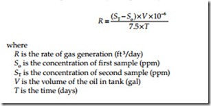
The rate of gas generation in gas space above the oil can be calculated by taking the sum of the gas concentrations of all combustible gases in the first and second samples and using the equation* given below:
Similarly, to determine the volume in gallons of fault gas dissolved in insulating oil, the following equation can be used:
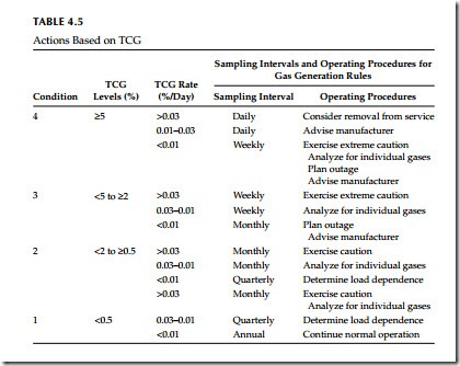
Assessing the Transformer Condition Using the TCGA in the Gas Space A new transformer should be tested within a week after energization. If it is not gassing and does not start gassing, subsequent tests should be made pro- gressively increasing intervals until the 12-month normal interval is reached. When sudden increases in the combustible gas quantities or generating rates in the gas space of an operating transfer occur and internal fault is suspected, IEEE Standard C57.104-1991 recommends the procedure to be used as shown in Table 4.5.
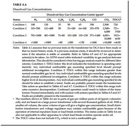
As indicated in Section 4.2.3.6 on TCGA evaluation, a new transformer should be tested for combustible gases within a week after energization, and continued with testing until the 12-month normal interval is reached. However, if there is no previous DGA history on the transformer, then it can be difficult to determine whether a transformer is operating normally or not. The IEEE Standard C57.104-1991 has established a four-level criterion to classify risk to transformers, when there is no previous DGA history, for continued use at various combustible gas levels. The IEEE criterion is shown in Table 4.6 below, which shows the individual gases and TDGA.
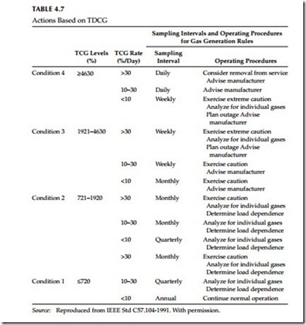
When sudden increases in the dissolved gas quantity of the oil in a normally operating transformer is noted and an internal fault is suspected, the IEEE
Standard C57.104-1991 recommends the procedure shown in Table 4.7. The IEEE procedure recommends the initial sampling intervals and operating procedure for various levels of TDCG and TDCG rate. An increasing gas generating rate means that the problem in the transformer may be severe and therefore a shorter sampling interval is recommended.
Fault Types and Associated Key Gases
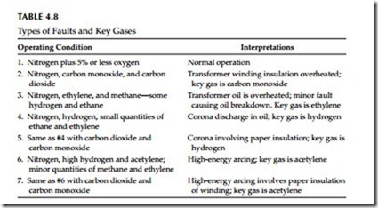
After the DGA has been obtained, then the next step is to determine the con- dition of the transformer. The evaluation has been simplified by looking at key gases and the associated condition as discussed in Table 4.8. Further, the
use of combustible gas ratios to indicate possible fault type was developed by Doernenburg and subsequently confirmed by Rogers on European system. These methods are known as Rogers ratio and Doernenburg ratio methods and are beyond the scope of this book.
