Introduction
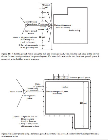
After the required grounding elements have been determined, they must be connected into a unified system [1]. Many different approaches can be taken, but the goal is the same: establish a low-resistance, low-inductance path to surge energy. Figure 20.1 shows a building ground system using a combination of ground rods and buried bare-copper radial wires. This design is appropriate when the building is large or located in an urban area. This approach also can be used when the facility is located in a high-rise building that requires a separate ground system. Most newer office buildings have ground systems designed into them. If a compre- hensive building ground system is provided, use it. For older structures (constructed of wood or brick), a separate ground system will be needed.
Figure 20.2 shows another approach in which a perimeter ground strap is buried around the building and ground rods are driven into the earth at regular intervals (2.2 times the rod length). The ground ring consists of a one-piece copper conductor that is bonded to each ground rod.
If a transmission or microwave tower is located at the site, connect the tower ground system to the main ground point via a copper strap. The width of the strap must be at least 1% of the length and, in any event, not less than 3 in. wide. The building ground system is not a substitute for a tower ground system, no matter what the size of the tower. The two systems are treated as independent elements, except for the point at which they interconnect.
Connect the utility company power-system ground rod to the main facility ground point as required by the local electrical code. Do not consider the building ground system to be a substitute for the utility company ground rod. The utility rod is important for safety reasons and must not be disconnected or moved. Do not remove any existing earth ground connections to the power-line neutral connection. To do so may violate local electrical code.
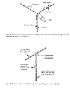
Bury all elements of the ground system to reduce the inductance of the overall network. Do not make sharp turns or bends in the interconnecting wires. Straight, direct wiring practices will reduce the overall inductance of the system and increase its effectiveness in shunting fast-rise-time surges to earth. Figure 20.3 illustrates the interconnection of a tower and building ground system. In most areas, soil conductivity is high enough to permit rods to be connected with no. 6 or larger bare-copper wire. In areas of sandy soil, use copper strap. A wire buried in low-conductivity, sandy soil tends to be inductive and less effective in dealing with fast-rise-time current surges. As stated previously, make the width of the ground strap at least 1% of its overall length. Connect buried elements of the system as shown in Figure 20.4.
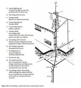
For small installations with a low physical profile, a simplified grounding system can be implemented, as shown in Figure 20.5. A grounding plate is buried below grade level, and a ground wire ties the plate to the microwave tower mounted on the building.
Bulkhead Grounding
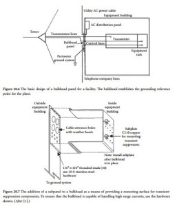
The bulkhead panel is the cornerstone of an effective facility grounding system [1]. The concept of the bulk- head is simple: establish one reference point to which all cables entering and leaving the equipment building are grounded and to which all transient-suppression devices are mounted. Figure 20.6 shows a typical bulkhead installation for a broadcast or communications facility. The panel size depends on the spacing,
number, and dimensions of the coaxial lines, power cables, and ther conduit entering or leaving the building.
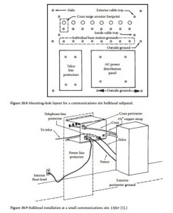
To provide a weatherproof point for mounting transient-suppression devices, the bulkhead can be modified to accept a subpanel, as shown in Figure 20.7. The subpanel is attached so that it protrudes through an opening in the wall and creates a secondary plate on which transient suppressors are mounted and grounded. A typical cable/suppressor-mounting arrangement for a communications site is shown in Figure 20.8. To handle the currents that may be experienced during a lightning strike or large transient on the utility company ac line, the bottommost subpanel flange (which joins the subpanel to the main bulkhead) must have a total surface-contact area of at least 0.75 in.2 per transient suppressor.
Because the bulkhead panel will carry significant current during a lightning strike or ac line distur- bance, it must be constructed of heavy material. The recommended material is 1/8-in. C110 (solid cop- per) 1/2-hard. This type of copper stock weighs nearly 5-1/2 lb/ft2 and is rather expensive. Installing a bulkhead, although sometimes difficult and costly, will pay dividends for the life of the facility. Use 18-8 stainless-steel mounting hardware to secure the subpanel to the bulkhead.
Because the bulkhead panel establishes the central grounding point for all equipment within the building, it must be tied to a low-resistance (and low-inductance) perimeter ground system. The bulk- head establishes the main facility ground point, from which all grounds inside the building are referenced. A typical bulkhead installation for a small communications site is shown in Figure 20.9.
Bulkhead Panel
A properly installed bulkhead panel will exhibit lower impedance and resistance to ground than any other equipment or cable grounding point at the facility [1]. Waveguide and coax line grounding kits should be installed at the bulkhead panel as well as at the tower. Dress the kit tails downward at a straight 45° angle using 3/8-in. stainless-steel hardware to the panel. Position the stainless-steel lug at the tail end,
flat against a cleaned spot on the panel. Joint compound will be needed for aluminum and is recom- mended for copper panels.
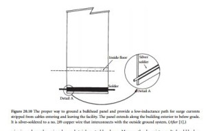
Because the bulkhead panel will be used as the central grounding point for all the equipment inside the building, the lower the inductance to the perimeter ground system, the better. The best arrangement is to simply extend the bulkhead panel down the outside of the building, below grade, to the perimeter ground system. This will give the lowest resistance and the smallest inductive voltage drop. This approach is illustrated in Figure 20.10.
If cables are used to ground the bulkhead panel, secure the interconnection to the outside ground system along the bottom section of the panel. Use multiple no. 1/0 or larger copper wire or several solid- copper straps. If using strap, attach with stainless-steel hardware, and apply joint compound for aluminum bulkhead panels. Clamp and Cadweld, or silver-solder for copper/brass panels. If no. 1/0 or larger
wire is used, employ crimp lug and stainless-steel hardware. Measure the dc resistance. It should be less than 0.01 Ω between the ground system and the panel. Repeat this measurement on an annual basis.
If the antenna feed lines do not enter the equipment building via a bulkhead panel, treat them in the following manner:
• Mount a feed-line ground bar on the wall of the building approximately 4 in. below the feed-line entry point.
• Connect the outer conductor of each feed line to the feed-line ground bar using an appropriate grounding kit.
• Connect a no. 1/0 cable or 3- to 6-in.-wide copper strap between the feed-line ground bar and the external ground system. Make the joint a Cadweld or silver-solder connection.
• Mount coaxial arrestors on the edge of the bar.
• Weatherproof all connections.
Lightning Protectors
A variety of lightning arrestors are available for use on coaxial transmission lines, utility ac feeds, and telephone cables. The protector chosen must be carefully matched to the requirements of the application. Do not use air-gap protectors because these types are susceptible to air pollution, corrosion, temperature, humidity, and manufacturing tolerances. The turn-on speed of an air gap device is a function of all of the foregoing elements. A simple gas-tube-type arrestor is an improvement, but neither of these devices will operate reliably to protect shunt-fed cavities, isolators, or receivers that include static drain inductors to ground (which most have). Such voltage-sensitive crowbar devices are short-circuited by the dc path to ground found in these circuits. The inductive change in current per unit time (Δdi/dt) voltage drop is usually not enough to fire the protector, but it can be sufficient to destroy the inductor and then the receiver front end. Instead, select a protector that does not have dc continuity on the coaxial center pin from input to output. Such units have a series capacitor between the gas tube and the equipment center pin that will allow the voltage to build up so that the arrestor can fire properly.
Typical Installation
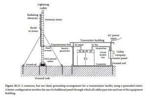
Figure 20.11 illustrates a common grounding arrangement for a remotely located grounded-tower (FM, TV, or microwave radio) transmitter plant. The tower and guy wires are grounded using 10-ft-long cop- per-clad ground rods. The antenna is bonded to the tower, and the transmission line is bonded to the tower at the point where it leaves the structure and begins the horizontal run into the transmitter building. Before entering the structure, the line is bonded to a ground rod through a connecting cable. The transmitter itself is grounded to the transmission line and to the ac power-distribution system ground. This, in turn, is bonded to a ground rod where the utility feed enters the building. The goal of this arrangement is to strip all incoming lines of damaging overvoltages before they enter the facility. One or more lightning rods are mounted at the top of the tower structure. The rods extend at least 10 ft above the highest part of the antenna assembly.
Such a grounding configuration, however, has built-in problems that can make it impossible to pro- vide adequate transient protection to equipment at the site. Look again at the example. To equipment inside the transmitter building, two grounds actually exist: the utility company ground and the antenna ground. One ground will have a lower resistance to earth, and one will have a lower inductance in the connecting cable or copper strap from the equipment to the ground system.
Using the Figure 20.11 example, assume that a transient overvoltage enters the utility company meter panel from the ac service line. The overvoltage is clamped by a protection device at the meter panel, and the current surge is directed to ground. But which ground, the utility ground or the antenna ground?
The utility ground surely will have a lower inductance to the current surge than the antenna ground, but the antenna probably will exhibit a lower resistance to ground than the utility side of the circuit. Therefore, the surge current will be divided between the two grounds, placing the transmission equip- ment in series with the surge suppressor and the antenna ground system. A transient of sufficient poten- tial will damage the transmission equipment.
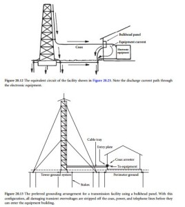
Transients generated on the antenna side because of a lightning discharge are no less troublesome. The tower is a conductor, and any conductor is also an inductor. A typical 150-ft self-supporting tower may exhibit as much as 40 μH inductance. During a fast-rise-time lightning strike, an instantaneous volt- age drop of 360 kV between the top of the tower and the base is not unlikely. If the coax shield is bonded to the tower 15 ft above the earth (as shown in the previous figure), 10% of the tower voltage drop (36 kV) will exist at that point during a flash. Figure 20.12 illustrates the mechanisms involved.
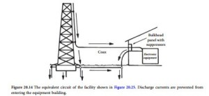
The only way to ensure that damaging voltages are stripped off all incoming cables (coax, ac power, and telephone lines) is to install a bulkhead entrance panel and tie all transient-suppression hardware to it. Configuring the system as shown in Figure 20.13 strips away all transient voltages through the use of a single-point ground. The bulkhead panel is the ground reference for the facility. With such a design, sec- ondary surge current paths do not exist, as illustrated in Figure 20.14.
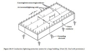
Protecting the building itself is another important element of lightning surge protection. Figure 20.15 shows a common system using multiple lightning rods. As specified by NFPA 78, the dimensions given in the figure are as follows:
• A = 50-ft maximum spacing between air terminals
• B = 150-ft maximum length of a coursing conductor permitted without connection to a main perimeter or downlead conductor
• C = 20- or 25-ft maximum spacing between air terminals along an edge
Checklist for Proper Grounding
A methodical approach is necessary in the design of a facility ground system. Consider the following points:
1. Install a bulkhead panel to provide mechanical support, electric grounding, and lightning protection for coaxial cables, power feeds, and telephone lines entering the equipment building.
2. Install an internal ground bus using no. 2 or larger solid-copper wire. (At transmission facilities, use copper strap that is at least 3 in. wide.) Form a star grounding system. At larger installations, form a star-of-stars configuration. Do not allow ground loops to exist in the internal ground bus. Connect the following items to the building internal ground system:
• Chassis racks and cabinets of all hardware
• All auxiliary equipment
• Battery charger
• Switchboard
• Conduit
• Metal raceway and cable tray
3. Install a tower earth ground array by driving ground rods and laying radials as required to achieve a low earth ground impedance at the site.
4. Connect outside metal structures to the earth ground array (towers, metal fences, metal buildings, and guy-anchor points).
5. Connect the power-line ground to the array. Follow local electrical code to the letter.
6. Connect the bulkhead to the ground array through a low-inductance, low-resistance bond.
7. Do not use soldered-only connections outside the equipment building. Crimped, brazed, and exothermic (Cadwelded) connections are preferable. For a proper bond, all metal surfaces must be cleaned, any finish removed to bare metal, and surface preparation compound applied (where necessary). Protect all connections from moisture by appropriate means (sealing compound and heat-sink tubing).
