Starter drives
Most diesel motors feature positive engagement drives energized by the solenoid. The solenoid is usually mounted piggyback on the frame and the pinion moved by means of a pivoted yoke (Fig. 11-20).
Regardless of mechanical differences between types, all starter drives have these functions:
• The pinion must be moved laterally on the shaft to engage the flywheel.
• The pinion must be allowed to disengage when flywheel rpm exceeds pin- ion rpm.
• The pinion must be retracted clear of the flywheel when the starter switch is opened.
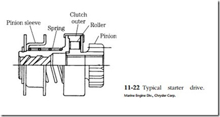
Figure 11-22 illustrates a typical drive assembly. The pinion moves on a helical thread. Engagement is facilitated by a bevel on the pinion and the ring gear teeth of the flywheel. Extreme wear on either or both profiles will lock the pinion.
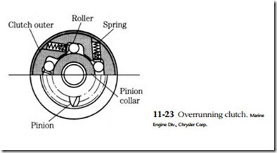
The clutch shown employs ramps and rollers. During the motor drive phase the rollers are wedged into the ramps (refer to Fig. 11-23). When the engine catches, the rollers are freed and the clutch overruns. Other clutches employ balls or, in a few cases, ratchets. The spring retracts the drive when the solenoid is deactivated.
Inspect the pinion teeth for excessive wear, and chipping. Some battering is nor- mal and does not affect starter operation. The clutch mechanism should be disassembled (if possible), cleaned, and inspected. Inspect the moving parts for wear or deformation, with particular attention to the ratchet teeth and the ramps. Lubricate with Aero Shell 6B or the equivalent. Sealed drives should be wiped with a solvent- wetted rag. Do not allow solvent to enter the mechanism, because it will dilute the lubricant and cause premature failure. Test the clutch for engagement in one direction of pinion rotation and for disengagement in the other.
Adjustment of the pinion throw is important to ensure complete and full mesh at the flywheel. Throw is measured between the pinion and the stop ring as shown in Fig. 11-24. Adjustment is by adding or subtracting shims at the solenoid housing (Fig. 11-25), moving the solenoid mounting bolts in their elongated slots, or turning the yoke pin eccentric.

