This chapter describes power requirements, mounting provisions, and alignment procedures for installing diesel engines in motor vehicles, stationary applications, and small boats. What I have tried to do here is to provide information that does not have wide currency, but is so critical that it makes or breaks the installation. Vendor catalogs serve for other aspects of the job, such as radiator/keel cooler sizing, selection of anti-vibration mounts, and sound-proofing techniques.
Trucks and other motor vehicles
Normally, installation is a bolt-on proposition, but things become complex when engines or transmissions are not as originally supplied.
Power requirements
Operators often judge a truck’s power, or lack of it, by how fast the truck runs. In other words, operators look at maximum rated horsepower available at full governed rpm. But expected road speeds may be unrealistic. For example, numerically low axle ratios can, up to a point, increase top speed, but at the cost of reduced acceleration and less startability, a term that is defined below. Other factors that influence top speed are loaded weight, road conditions, wind resistance (which can double when loads are carried outside of the vehicle bodywork), and altitude. Naturally aspirated engines lose about 3% of their rated power per 1000 ft of altitude above sea level.
The desired cruising speed should be 10% to 20% below rated horsepower rpm, to provide a reserve of power for hill climbing and passing. When fuel economy is a primary consideration, the cruising speed can be set even lower. The power required at cruising speed is the engine’s net horsepower.
Other factors to consider are the ability of the vehicle to cope with grades. Startability is expressed as the percentage grade the vehicle can climb from a dead stop. A fully loaded general-purpose truck should be able to get moving up a 10%
grade in low gear. Off-road vehicles should be able to negotiate 20% grades, with little or no clutch slippage. Startability is a function of the lowest gear ratio and the torque available at 800–1000 rpm.
Gradeability is the percentage grade a truck can climb from a running start while holding a steady speed. No vehicle claiming to be self-propelled should have a gradeability of less than 6%. Gradeability depends upon maximum torque the engine is capable of multiplied by intermediate gearing.
Caterpillar and other engine manufacturers can provide assistance for sizing the engine to the particular application. But it’s useful to have some understanding of how power requirements are calculated.
The power needed to propel a vehicle is the sum of driveline losses, air resistance, rolling resistance, and grade resistance.
driveline losses 1 – driveline eff. X hpair + hproll + hpgrade
driveline eff. overall efficiency of the driveline, calculated on the assumption that each driven element—main transmission, auxiliary transmission, and rear axle— imposes an efficiency penalty of 4%. Thus, a truck with a single transmission and one driven rear axle would have an overall driveline efficiency of 92% (0.96 X 0.96 92%).
hpair air resistance hp (mph3 –: 375) X 0.00172 X modifier X frontal area Without some sort of provision to smooth airflow, the truck has a modifier of1.0. If an aerodynamic device is fitted, the modifier is 0.60. For purposes of our cal- culation, frontal area width in feet X (height in feet – 0.75 ft).
hproll rolling resistance hp GVW X mph X Crr
where GVW represents the gross vehicle weight in pounds, and Crr represents the rolling resistance. This latter figure depends upon tire type: on smooth concrete, bias-ply tires have a Crr of 17 lb/ton and radial tires 11 lb/ton. Low-profile tires do even better.
hpgrade grade hp (grade percentage X GVW X mph) –: 37,500
Motor mounts
In most instances, the technician merely bolts the engine down to a factory-designed mounting system. But there are times when engine-mounting provisions cannot be taken for granted.
Vehicle engines traditionally use a three-point mounting system, with a single point forward around which the unit can pivot, and with two points at the flywheel housing or transmission. For some engines the forward mount takes the form of an extension, or trunnion, at the crankshaft centerline. A sleeve locates the trunnion lat- erally, while permitting the engine to rotate. In order to simplify mounting and give more control over resiliency, other engines employ a rigid bracket bolted to the timing cover and extending out either side to rubber mounts on the frame.
Rear mounts normally bolt to the flywheel cover and function to locate the engine fore and aft, while transmitting the torque reaction to the vehicle frame. In order to control vibration, mount stiffness must be on the order of one-tenth of frame stiffness.
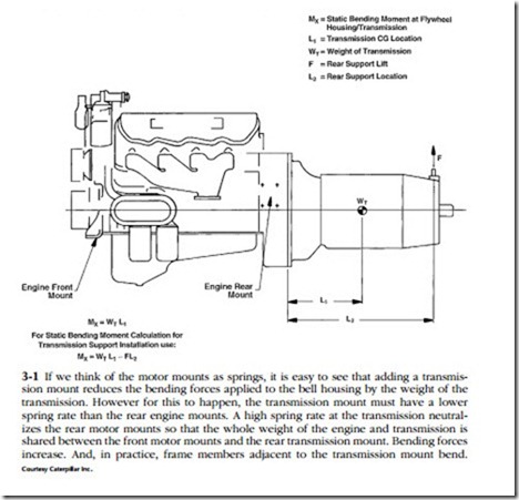
On many applications the transmission cantilevers off the engine block without much additional support. The bending moment imposed by the overhung load on the flywheel housing should be calculated and compared against factory specs for the engine. Figure 3-1 illustrates the calculation for a transmission that receives some additional support at the rear with a third mount.
The third mount should have a vertical rate (lb/in. of deflection) considerably lower than the vertical rate of the rear engine mounts. A transmission mount with a higher spring rate than the engine mounts increases the bending moment. In addi- tion, the high spring rate is almost sure to deflect the truck frame and, in the process, generate high forces on the engine/transmission package.
Off-road trucks present special problems, since engines and transmissions are sub- ject to high gravity loads and the potential for frame distortion. Another factor that needs to be taken into consideration is that motor mounts must be able to absorb the torque reactions generated by the ultra-low gear ratios often specified for these vehicles.
