Stationary engines
Power requirements
Power requirements for stationary applications can be difficult to calculate. Wherever possible, engine selection should be based upon experience and verified by tests in the field.
Caterpillar rates its industrial engines on a five-tier format based on load- factor duty cycle, annual operating hours, and expected time between overhaul. The load factor is a measure of the actual power output of the engine that, at any particular throttle setting, depends upon load. For example, an engine set to produce 300 hp will produce 50 hp under a 50-hp load, 100 hp under a 100-hp load, and so on. Fuel consumption increases with load demand. The load factor indicates how hard the engine works, and is calculated by comparing actual fuel usage with no-load usage at the throttle setting appropriate for the application.
• Industrial A—100% duty cycle under full load at rated rpm. Applications include pipeline pumping stations and mixing units for oilfield service.
• Industrial B—Maximum 80% duty cycle. Typical applications are oilfield rotary-table drives and drilling-mud, and cement pumps
• Industrial C—Maximum duty cycle 50%, with one hour at full load and speed, followed by one hour at reduced demand. Applications include off- road trucks, oilfield hoisting, and electric power generation for oil rigs.
• Industrial D—Maximum duty cycle not to exceed 10%, with up to 30 minutes of full load and power followed by 1 hour at part throttle. Used for offshore cranes and coiled-tubing drilling units where loads are cyclic.
• Industrial E—Maximum duty cycle not to exceed 5%, with no more than 15 minutes at full power, followed by one hour at reduced load. E-rated engines may need to develop full power at starting or to cope with short- term emergency demands.
All things equal, an oversized engine works at a lower load factor and should run longer between overhauls. Power in reserve also means that overloads can be accommodated without loss of rpm.
Power, the measure of the work the engine performs over time, is only part of the picture. Engines also need to develop torque, an instantaneous twisting force on the flywheel, commensurate with the torque imposed by sudden loads. Load- induced torque slows and, in extreme cases, stalls out the engine. The relationship between engine torque and load torque is known as the torque rise.
If peak torque demand were twice that of engine torque, the torque-rise percentage would be only 50% and we could expect the engine to stumble and stall under the load. If, on the other hand, engine torque equaled load-induced torque,
the engine would absorb the load without protest. However, high-torque-rise engines stress drivelines, mounts, and related hardware. Some compromise must be made.
It should also be noted that not all driven equipment impose sudden torque rises. For example, centrifugal pumps and blowers cannot lug an engine because the effi- ciency of these devices falls off more quickly with reduced speed than engine torque. Gen-sets run at constant speed and do not require much by way of torque rise. On the other hand, positive-displacement pumps generate high torques when pump output is throttled.
As the engine slows under load, the governor increases fuel delivery. Naturally aspirated engines respond quickly, since the air necessary to burn the additional fuel is almost immediately available. Turbocharged engines exhibit a perceptible lag as the turbo spools up. But naturally aspirated engines have difficulty in meeting emis- sions limits and, for the same power output, are heavier and more expensive than turbocharged models. Some industrial engines employ a small turbocharger for low- speed responsiveness and a second, larger unit for maximum power. Variable geometry turbocharging (VGT) virtually eliminates lag time.
The black smoke accompanying turbo lag can be reduced with an air/fuel ratio controller. Also known as a smoke limiter, the device limits fuel delivery until suffi- cient boost is present for complete combustion. Adjustment is a trade-off between transient smoke and engine responsiveness.
The engine manufacturer normally has final say on the mounting configuration that may consist of parallel rails or, in the case of several Caterpillar oilfield engines, a compound base. In the later arrangement the engine bolts on an inner base, which is suspended on springs above the outer base. The technician has the responsibility to see that engine mounts permit thermal growth and that engine and driven element are in dead alignment.
Thermal expansion
Cast iron “grows” less than steel when exposed to heat. The coefficient of expansion is 0.0000055 for cast iron and 0.0000063 for steel. A 94-in.-long iron engine block will elongate 0.083 in. as its temperature increases from 50° to 200° F. Under the same temperature increase, 94-in. steel mounting rails grow 0.089 in. These parts must be free to expand.
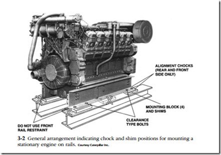
Caterpillar 3508, 3512, and 3516 oilfield engines mount on a pair of factory- supplied rails bolted to the oil pan. Standard procedure is to tie the engine down to the rail with a fitted bolt, that is, a bolt inserted with a light push fit into a reamed hole at the right rear corner of the oil pan. This bolt provides a reference point for alignment. Other engine-to-rail mounting bolts fit into oversized holes in the rails to allow for expansion. Clearance-type bolts should be 0.06 in. smaller than the diam- eter of the holes in the rails (Fig. 3-2). Chocks, used as an installation convenience to position the engine on the rails, must not constrain thermal expansion.
Alignment
Begin by cleaning all mating surfaces to remove rust, oxidation, and paint. If rubber couplings are present, remove them. It may be necessary to fabricate a dial-indicator holder from 11/2-in. steel plate that can be bolted down to the machine. While this
sounds like overkill, many commercially available magnetic indicator holders lack rigidity. Flex in the holder can be detected by the failure of the indicator to return to zero when the shaft is rotated back to the initial measurement position.
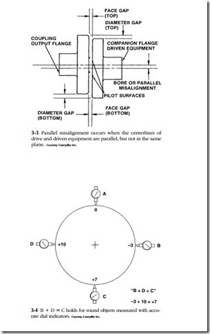
Parallel misalignment occurs when the centerlines of the engine crankshaft and driven equipment are parallel, but not in the same plane (Fig. 3-3). Mount a dial indi- cator on the engine flange with the point against the driven flange. Make several readings while a helper bars over the crankshaft in the normal direction of rotation.
The driven, or load, shaft should, as a general rule, be higher than the engine shaft. Engine main bearings typically have greater clearance than driven-equipment bearings. Until the engine starts, the crankshaft rests on the main-bearing caps, one or two thousandth of an inch below its running height. In addition, some allowance must be made for vertical expansion of the engine at operating temperature, which is nearly always more pronounced than the vertical expansion of the driven machinery.
Figure 3-4 illustrates a method of verifying dial-indicator readings on the outer diameters (ODs) of flanges and other circular objects. Zero the indicator at A in the drawing and, as the flange is rotated, make subsequent readings 90° apart. If the indicating surface is clean and the instrument mount secure, the needle will return to zero in the A position and B + D readings will equal C.
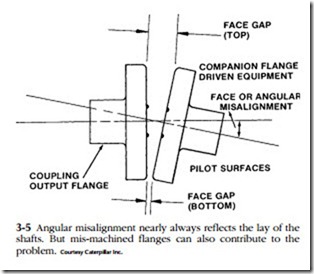
Measurement of angular misalignment can be made with a feeler gauge (Fig. 3-5). Once the problem is corrected by shimming, bolt the flanges together and verify that the crankshaft can move fore and aft a few thousandths of an inch against its thrust bearing.
Parallel and angular misalignment can originate in driveline hardware, which rarely gets the scrutiny it deserves (Fig. 3-6). Parallel misalignment, called bore runout, refers to the lack of concentricity between the bore of a hub and the shaft centerline. Angular misalignment occurs when the mating face of a flange is not perpendicular with the shaft centerline. This sort of machining error is known as face runout.
Bore runout between the flywheel inner diameter (ID) ) and the crankshaft pilot- bearing should be no more than 0.002 in., and no more than 0.005 in. for adaptors that make up to the flywheel. The maximum face runout for driveline components is 0.002 in.
Generators, transmissions, and other close-coupled driven elements that bolt directly to the flywheel housing can also suffer from misalignment. As a check, loosen the bolts securing the unit to the flywheel housing and measure the gap between the parts with a feeler gauge. The interfaces should be within 0.005 in. of parallel.
It is good practice to determine the bending moment of components cantilevered off the flywheel housing, as described previously under truck “Motor mounts.”
Use brass shims (steel shims expand as they rust) and tighten the typical four- bolt mounting as shown in Fig. 3-7. Grade-8 hold-down bolts are torqued to speci- fication, an operation that requires a large torque wrench and a torque multiplier in the form of a 3- or 4-ft cheater bar.


