Unbalanced LVRT
In reality, the unbalanced grid faults (e.g., one-phase grounded or two-phase con- nected) are more likely to happen. In these cases, the LVRT operation of the grid side converter is more complicated compared to the balanced fault condition (three-phase grounded). During the unbalanced LVRT, the types and location of grid faults, the connection of transformer windings, and the power control strategies of the converter dramatically change the loading of power switching devices. Therefore, the operation conditions for unbalanced grid fault have to be carefully specified.
A. Propagation of Voltage Dips
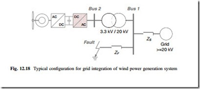
A typical configuration for grid integration of wind turbine is shown in Fig. 12.18, in which a Dy transformer is used to interface the power converter output on Bus 2
(e.g. 3.3 kV) and the distribution line of wind farm on Bus 1 (e.g. 20 kV). A short-circuit fault in the grid integration system will cause voltage dips on Bus 1 and Bus 2.
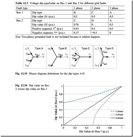
Defining the voltage dip value DN which represents the lowest phase voltage amplitude in p.u. on the Bus N. Three typical grid faults: one-phase grounded (1 phase), two-phase connected (2 phase), and three-phase grounded (3 phase) with the same dip values are assumed to happen respectively on Bus 1 (D1 = 0.5, no phase jump). Due to the Dy connection of the transformer windings, the voltage dips propagated from Bus 1 may look different on Bus 2. As summarized in Table 12.3, in which the voltage dip type and dip value on Bus 1 and the corresponding voltage characteristics on Bus 2 are included. The voltage dip types A-D are defined as phasor diagrams in Fig. 12.19 respectively.
It can be seen that the three-phase balanced grid fault (3 phase) on Bus 1 propagates the same dip type and dip value on Bus 2. While the unbalanced grid faults (1 phase and 2 phase) with the same dip value on Bus 1 cause different dip types and dip values on Bus 2, which is monitored by the grid side converter and result in different amount of delivered reactive currents to help the grid to recover from faults.
The whole range of voltage dip value on Bus 1 in relation to the corresponding dip value on Bus 2 is shown in Fig. 12.20, in which balanced (3 phase) and unbalanced (1 phase and 2 phase) grid faults are indicated respectively. It is clear that the balanced grid fault on Bus 1 will propagate the same dip value on Bus 2. While the single-phase unbalanced grid fault happened on Bus 1 has a higher dip value when propagating on Bus 2, and the two-phase unbalanced grid fault on Bus 1 has lower dip value when propagating on Bus 2.
For simplicity of the analysis, only the single-phase grounded fault on Bus 1 is chosen in this special topic as an example of the unbalanced LVRT. The injected reactive current to the grid by wind power converter is set according to the lowest phase voltage amplitude on Bus 2 referring to the grid demands. It is required that the active/reactive current generated by the converters only contain positive sequence component, and the negative sequence currents are controlled to be zero. The behavior of converters under various LVRT is still a continuous discussion for the future grid standards.
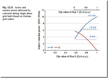
B. Operation Status Under Single-Phase Unbalanced Grid Fault The active/reactive power delivered by the grid side converter under single phase unbalanced grid voltage dip is shown in Fig. 12.21, where the horizontal axis represents the voltage dip values on Bus 2. It is noted that the single-phase voltage dip on Bus 1 (type B) propagates two-phase voltage dip on Bus 2 (type C), whose dip value D2 cannot be lower than 0.577 due to the characteristic of Dy trans- former. The situations of 12 m/s wind speed (10 MW generated power), 10 m/s (6.3 MW generated power) and 8 m/s (3.2 MW generated power) are indicated respectively.
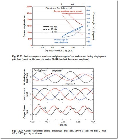
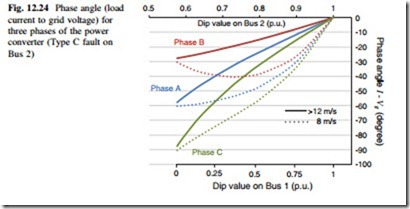
The current amplitude as well as the phase angle under single-phase unbalanced grid fault is shown in Fig. 12.22, where the phase angle represents the angle between the load current and grid voltage of A phase in the type C grid fault definition diagram (Fig. 12.19). It can be seen that the current amplitude and phase angle dramatically change with the variation of grid voltage and wind speed.
As an example, Fig. 12.23 shows the grid voltage, load current as well as instantaneous active/reactive power of the wind power converter undergoing single-phase unbalanced grid fault on Bus 1. The wind speed is at 10 m/s (6.3 MW), the dip value D1 is at 0 p.u. (0.577 p.u. when propagated to Bus 2), the positive sequence active current is at 0.533 p.u. and the reactive current is at 0.864 p.u. according to the German grid codes.
It can be seen that the grid voltage on Bus 2 is consistent with the type C fault definition in Fig. 12.19, and the currents in the converters are symmetrical among three phases, which means only positive sequence currents are generated. Due to the existence of negative sequence voltage, there is a 100 Hz fluctuation in the delivered active- and reactive power of converter, which is assumed to be absorbed by the DC bus chopper.
By looking at the phasor diagram definition for grid voltage dip type C in Fig. 12.19, it is interesting to see that when the single-phase grid fault is presented on Bus 1, there is a phase shift in the voltage of phase B and C on Bus 2, and thereby the angle between each phase voltage is no longer 120°. On the other hand it is required that only positive sequence current should be delivered by the wind power converter, therefore the angle between each phase current is still kept at 120°, as shown in Fig. 12.23.
Figure 12.24 shows the phase angles (between phase voltage and current) for the three phases of wind power converter in relation to the voltage dips when single-phase unbalanced grid fault is presented. The conditions with wind speeds of 12 and 8 m/s are indicated respectively.
As mentioned before, the phase angles as well as the voltage/current amplitude are closely related to the loading of power switching devices. From Figs. 12.23 and 12.24, it can be seen that the voltage amplitude and phase angle of the three phases of converter are quite different from each other, therefore, the device loss and thermal distribution should also be different for each phase of the converter when undergoing unbalanced LVRT.
C. Loss Analysis Under Single-Phase Unbalanced Grid Fault
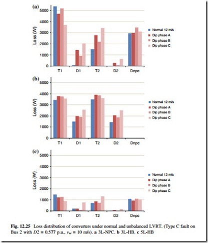
The loss distribution of the power switching devices under normal operation (with wind speed of 12 m/s), and the loss distribution for the three phases of converters under unbalanced LVRT, are compared in Fig. 12.25. The 10 % higher DC bus voltage is applied for LVRT condition. It can be seen that, the LVRT operation still imposes the diodes and inner switches with significantly larger losses than the most stressed normal operation condition, and the loss distribution among the three phases is asymmetrical for each topology.
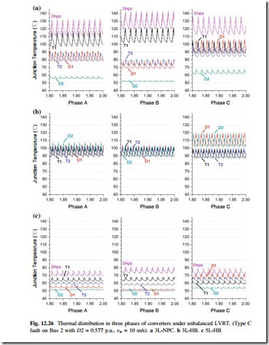
D. Thermal Distribution Under Single-Phase Unbalanced Grid Fault The simulated junction temperatures for the three phases of converters are shown in Fig. 12.26, in which the converters are undergoing unbalanced LVRT (Type C fault on Bus 2 with D2 = 0.577 p.u., vw = 10 m/s). It can be seen that for the 3L-NPC topology, the thermal distribution is unequal not only among the devices but also among the three phases. Phase B has a more stressed Dnpc and T1, while phase A
and phase C have more stressed T2, D1, and D2. It is found that Dnpc in phase B is the most stressed device of the converter under the given condition.
For the 3L-HB topology, the thermal distribution is more equal both among the devices and the three phases, D1/D2 in phase C is the most stressed devices of the converter.
For the 5L-HB converter, thermal distribution tendency is similar to the 3L-NPC topology, but the inequity among the devices and the three phases are significantly improved.
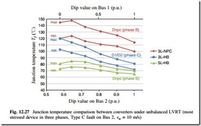
The junction temperature comparison of the most stressed power device among the three phases in each of the converter topology is shown in Fig. 12.27, in which the fluctuation range of the junction temperature is indicated. Again, 3L-HB and 5L-HB topologies show advantages under unbalanced LVRT condition (Type C fault on Bus 2, vw = 10 m/s).
