Analog versus digital
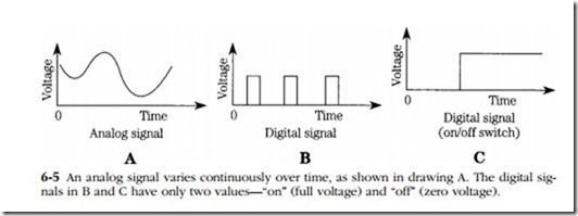
Engine management systems communicate through voltage changes that take an analog or digital form. Analog signals fluctuate over time, as shown by the waveform voltage in Fig. 6-5. The instantaneous value—the value of the signal at any moment in time—conveys data. Voltage spikes, bad grounds, and loose connections seriously com- promise the ability of analog circuits to act as reliable messengers. Even so, most sensors are analog devices that respond to changes in pressure, temperature, or fluid level by varying their internal resistance. Supply voltage is constant (normally 5V +/− 0.5V), and output voltage changes as sensor resistance increases or diminishes. In order to process the analog data, the computer converts these voltages into digital form.
Digital signals have only two states—“on” corresponding to 1, and “off,” corresponding to 0. All the computer need do is to discriminate between binary on and off states, or bits. Depending upon the system, a string of 8, 16, or 32 bits make up a word, which conveys information. Circuit noise can destroy part of a word, making it unintelligible, but noise generally does not alter the meaning of complete words in the systematic fashion required to fool the computer.
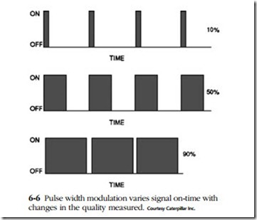
A digital signal can also communicate data by means of pulse width modulation (PWM). As illustrated in Fig. 6-6, the width of the signal represents its duration expressed as the ratio of the percentage of “on time” divided by the percentage of “off-time.” The most common application of PWM is for throttle position sensors that typically generate a pulse width of 15–20% at idle and 90% or more at full throttle.

