INTERNAL COMBUSTION ENGINES
The common feature of all reciprocating engines is a cylindrical chamber housing a piston. In its most basic form the engine comprises a single cylinder sealed at one end and open at the other end. A cylindrical-shaped disk of metal, the piston, is designed to fit closely within the cylinder to seal the open end, and this piston can move backwards and forwards easily within the cylinder. This it does in response to the pressure changes in the gas contained within the cylinder at various stages in the engine cycle. Meanwhile, air and fuel can be admitted into the sealed end of the cylinder, and exhaust gases removed after combustion through moveable valves. The outside of the piston is attached via a hinged lever to the main drive shaft of the engine. Movement of the piston in and out of the cylinder is converted via this hinged linkage into rotary motion of the main shaft and this rotary motion is used to derive power or electricity.
To convert chemical energy contained within a fuel into mechanical energy, an air–fuel mixture is admitted into the cylinder of the engine and ignited, causing a controlled explosion and a high-pressure impulse from which the power of the engine is derived. The pressure impulse forces the gases in the cylinder to expand, pushing the piston to the limit of its movement. This controlled explosion gives the engines its common name: the internal combustion engine.
1. Slow-speed engines are the most efficient engines for converting fuel energy via heat into rotary motion to generate electricity. Fuel cells, which turn chemical energy directly into electrical energy, can be more efficient.
Of the two common engine cycles, the four-stroke cycle is the most commonly used, particularly for small- and medium-size engines. A two-stroke cycle is employed is some very small engines because it can provide a high power-to-weight ratio. It is also often used in very large engines since it is capable of high efficiency and tolerating very poor fuels.
Both cycles are broadly similar in concept to the principle employed in the gas-turbine engine described in Chapter 4. Air is compressed and then fuel added and ignited, generating a hot, high-pressure gas from which energy can be extracted in the form of mechanical work. However, whereas the gas- turbine engine is continuously compressing air, mixing it with fuel and igniting the mixture, the piston engine carries these processes out sequentially.
Engine Cycles
The internal combustion engine is a thermodynamic heat engine, and as such belongs to the same category as steam turbines and gas turbines. However, the physical nature of the reciprocating engine is very different to that of the turbines. The reciprocating engine principle was developed in the latter half of the 19th century, though some primitive engines were in existence before that. Nikolaus Otto is generally credited with building the first four-stroke internal combustion engine in 1876. In doing so, he established the principle still in use today.
The Otto cycle engine employs a spark to ignite a mixture of air and, traditionally, gasoline2 compressed by the piston within the engine cylinder. This spark ignition causes an explosive release of heat energy that increases the gas pressure in the cylinder, forcing the piston outwards as the gas tries to expand. This explosion is the source of power, its force on the piston turning the crankshaft to generate rotary motion.
The Otto cycle was modified by Rudolph Diesel in the 1890s. In his version, air is compressed in a cylinder by a piston to such a high pressure that its temperature rises above the ignition point of the fuel, which is then introduced into the chamber and ignites spontaneously without the need for a spark. This rep- resents a simplification of the Otto cycle but is not without its complications, particularly from an emissions perspective.
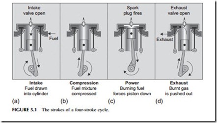
In a four-stroke engine each piston of the engine—and there can be a large number depending on the particular engine type and application—is equipped with at least two valves: one to admit air or an air–fuel mixture, and a second to exhaust spent gases after ignition. The opening and closing of these valves is mechanically synchronized with the movement of the piston backwards and forwards.
full power cycle. Starting with the piston at the top of its chamber, and the chamber empty, the first stroke is an intake stroke in which either air (diesel cycle) or a fuel and air mixture (Otto cycle), is drawn into the piston chamber by movement of the piston to expand the volume of the enclosed space (Figure 5.1) and the air or fuel–air valve is open. This valve closes at the end of the first stroke. The second stroke is a compression stroke during which the gases in the cylinder are compressed by the piston returning toward the top of its chamber. In the case of the Otto cycle, a spark ignites the fuel–air mixture at the top of this second stroke, creating an explosive expansion of the compressed mixture that forces the piston down again. This is the power cycle. In the diesel cycle fuel is intro- duced through a separate nozzle close to the top of the compression stroke, igniting spontaneously in the hot gas with the same effect. After the power stroke, the fourth stroke is the exhaust stroke during which the exhaust gases are forced out of the piston chamber through the second valve, which is now open. This closes at the end of the fourth stroke and the cycle begins again. In both spark-ignition and diesel engines a large flywheel attached to the crank- shaft stores angular momentum generated by the power stroke and this provides sufficient momentum to carry the crankshaft and piston through the three other stokes required for each cycle.
The shaft of an engine that is fitted with a single piston and cylinder will receive a power impulse once every two rotations, leading to a relatively uneven transfer of power. However, if the engine has multiple cylinders, the cycle of each can be staggered relative to the others so that they deliver their power sequentially, leading to a much more even rotational motion. For a four-stroke engine it is normal for four (or a multiple of four) pistons to be attached to the crankshaft, with one of each set of four timed to produce a power stroke while the other three move through different stages of their cycles. The introduction of
fuel and air and the removal of the exhaust gases are then controlled by valves that are mechanically timed to coincide with the various stages of the cycle on each cylinder.
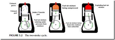
In a two-stroke engine, intake and exhaust strokes are not separate. Instead, fuel is forced into the piston chamber (intake) from an opening in the crankshaft casing toward the end of the power stroke, pushing out the exhaust gases through a second opening at the top of the chamber. The same stroke then com- presses the fuel–air mixture within the cylinder, the exhaust port having been closed by movement of the piston. This exhaust–compression stroke is then fol- lowed by ignition of the fuel and a power–expansion stroke, then a repeat of the cycle (Figure 5.2).
Two-stroke engines are simpler than four-stroke engines because they do not require valves. In addition, power is delivered by each cylinder at each revolution of the shaft rather than once every two revolutions. This means they can deliver more power for a similar weight.
Engine Size and Engine Speed
The speed at which a piston engine operates will usually depend on its size. In general, small units operate at the highest shaft rotational speed and large units at the lowest shaft speed. In addition, in most situations a piston engine–based power unit will have to be synchronized to an electricity grid operating at 50 Hz or 60 Hz, so the engine speed will also be determined by one or the other of these rates. So, for example, a 50 Hz high-speed engine will typically operate at 1000 rpm, 1500 rpm, or 3000 rpm, while the equivalent 60 Hz machine will operate at 1200 rpm, 1800 rpm, or 3600 rpm. These speeds allow the generators attached to the engines to synchronize with the grid operating frequency.
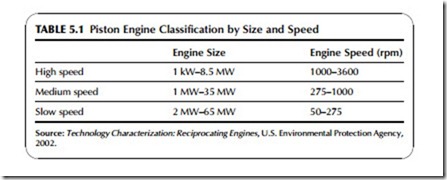
Engines are usually classified according to speed into one of three groups, high speed, medium speed and slow speed engines. High speed engines are the smallest and operate up to 3600 rpm. The largest slow speed engines may run as slow as 50 rpm. Typical speed and power ranges for each type of engine are shown in Table 5.1.
Engine performance varies with speed. High-speed engines provide the greatest power output as a function of cylinder size, and therefore the greatest power density. However, the larger, slower engines are more efficient and last longer. Thus, the choice of engine will depend very much on the application for which it is intended. Large and slow- or medium-speed engines are generally more suited to base-load generation, but it may be more cost effective to employ high-speed engines for backup service where the engines will not be required to operate for many hours each year.
In addition to standby service or continuous output base-load operation, piston engine power plants are good at load following. Internal combustion engines operate well under part-load conditions. For a gas-fired spark-ignition engine, output at 50% load is roughly 8–10% lower than at full load. The diesel engine performs even better, with output barely changing when load drops from 100% to 50%.


