Capacitors
Several different tests may be performed on power-factor correction capacitors to determine their suitability for service. From these, users may select tests that they deem practical and necessary. Factors that influence the selection of tests may be the type of banks, such as substation banks or dis- tribution lines, electrical arrangements, failure rate experiences, and others. NEMA Standards Publication CP1-1977, Section 6.06, “Field Test on Capacitor Units,” listed the two options: (1) checking new capacitor units before plac- ing in service and (2) after they have been placed in service. For historical perspective, the requirements for checking the capacitor units before placing them in service were the following:
Tests to Check the Condition of New Capacitor Units before Placing in Service Perform the following tests:
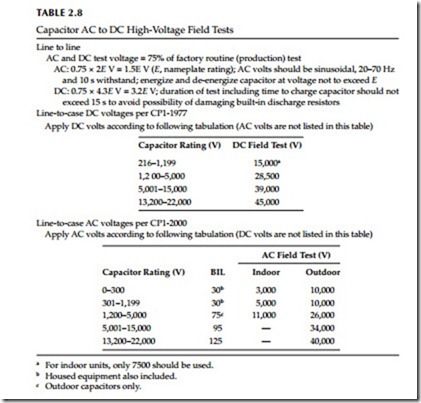
• Terminal-to-terminal AC or DC high-voltage test at 75% of factory routine (production) test voltage.
• Short-circuited terminal-to-case (two-terminal units only) per- form impulse and DC high-voltage test according to voltage rating table given in the old standard. This section also states, “Experience has shown that these tests are not necessary on all capacitor units.”
The most current standard, CP1-2000, lists only one option for checking the new capacitor units after they are placed in service. These requirements are the following.
Tests to Check the Condition of a Capacitor Unit after It Has Been in Service Serviceability of a capacitor unit may be determined by one or more of the following tests in case of trouble or after exposure to possible damage:
• Capacitance measurements by current measurement at known voltage and rated frequency, or by a low voltage capacitance meter. These tests will generally indicate a short-circuited capacitor or open-circuited capacitor.
• Line-to-line internal discharge resistor may be checked with a suit- able bridge or calculated from DC voltage and current readings.
• Line-to-case insulation resistance measurements may be made to deter- mine the condition of the insulating terminals and dielectric insulation
to case. The resistance measured should be not less than 1000 MΩ. This test is not applicable to single bushing capacitors. Measuring the line- to-case power factor or dielectric loss is another means of determining the condition of the line insulating terminals and insulation to case.
• Measurable characteristics of properly applied and installed capaci- tors, which are hermetically sealed, are not expected to change with time. Therefore, periodic testing may not be necessary. However,
operating conditions may change, resulting in damage and short life; hence, periodic inspection and check of such operating condi- tions as outlined previously in this section are highly desirable.
• Liquid tightness at 50°C may be used if manufacturer’s limit is not available.
NEMA standard CP1-2000 provides options that enable a user to develop a test program suitable to its needs. The discharge resistor measurements and calcu- lations from current measurements at low voltage can be compared readily with manufacturers’ values and serve as a reference for future comparison.
Current measurements at low voltage have proven value for two other purposes:
• Detection of short-circuited sections in a capacitor
• Predetermination and correction of unbalanced current in split-wye banks during installation
The test programs for substation and distribution lines have proved to be realistic during installation and in service situations. Table 2.8 references NEMA recommended test values in the older CP1-1977 and the latest CP1- 2000 standards.
