The cylinder head acts as the backing plate for the head gasket and must, above all, be rigid. Iron is the preferred material, although automotive and other light- duty engines often are fitted with aluminum heads. Because of its good conductivity, aluminum assists cooling and eliminates the steep thermal gradients that iron is heir to. In other words, aluminum heads are less likely to develop local hot spots.
But, in common with most other structural materials, the weight savings of aluminum come at the cost of rigidity. Aluminum has a third the density of iron and a third the rigidity. To achieve the same level of stiffness, an aluminum head would have to weigh as much as the iron head it replaces. Good design practice and closely spaced head bolts ameliorate the problem, but aluminum heads are always less rigid than their cast-iron equivalents.
And while aluminum can be heat-treated to T6 or T7 hardness, few manufacturers bother, since the benefits of heat treating disappear at high temperatures. The light-metal alloys in general use exhibit a rapid loss of strength at temperatures above 200°C (392°F). Overheating an engine is almost guaranteed to warp the head. To further complicate matters, cast-iron has a lower rate of thermal expansion than aluminum. When bolted to an iron block, an aluminum head tends to bow upward, reducing the clamping force on the gasket. This phenomenon is discussed in the section that deals with head straightening.
The cylinder head forms an important part of the cooling system. The water jacket should be cast with large passages that resist clogging. Some designs employ diverters, or baffles, to direct the coolant stream to valve seats and other critical areas. Standard practice is to integrate block and head cooling, but several industrial engines separate the two so that a blown head gasket does not contaminate the crankcase oil with antifreeze.
Fasteners—capscrews or studs—should be arranged symmetrically insofar as rocker pedestals, valve ports, and injector and glow-plug bosses permit.
A vast amount of development work was done in the 1920s and 30s on optimum combustion chamber shapes. The effort continues—with emphasis on control of emissions—but the main outlines of the problem and the alternatives appear to be firmly established.
The central problem is to provide a mechanism for mixing fuel with the air. The fuel spray must be dispersed throughout the cylinder so that all available oxygen takes part in the combustion process. As fuel droplets move away from the nozzle, the chances of complete combustion are progressively lessened. There is less oxygen available because some of the fuel has already ignited. In addition, the droplets shrink as they travel and successive layers of light hydrocarbons boil off.
Direct injection
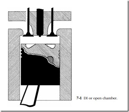
Direct Injection (DI) chambers, also called open or undivided chambers, resemble those used in carbureted engines (Fig. 7-1). These symmetrical chambers have small surface areas and, to reduce heat losses further, generally take the form of a cavity in the piston crown.
Until the advent of multiple-orifice, staged injectors and the high-pressure fuel systems necessary to support them, DI chambers compensated for poor fuel penetration by imparting energy to the air charge. Two mechanisms were involved: swirl and squish. The exit angle of the intake-valve seat imparted a spinning motion, or swirl, to incoming air stream. Squish was achieved by making the edges of the piston
crown parallel to the chamber roof. As the piston neared top dead center (tdc), air trapped between these two faces “squished” inward, toward the piston cavity.
Mixing was less than perfect, which resulted in ignition delay and rapid rises in cylinder pressure as the accumulated fuel charge exploded. As a result, DI was con- fined to stationary, heavy trucks and marine engines where noise, vibration, and exhaust smoke counted for less than fuel economy.
The breakthrough came in the late 1980s in the form of electronic injectors that sequenced fuel delivery to “soften” combustion and reduce ignition delay. Ultrahigh fuel pressures, coupled with orifice diameters as small as 0.12 mm, or twice the thick- ness of a human hair, atomize the fuel for better mixing. The fuel charge became the primary vehicle for mixing that, in some cases, enabled designers to eliminate the pumping losses associated with generating air turbulence. DI also opened the way for massive power increases. By substituting DI for the Ricardo Comet V cylinder head originally fitted, enlarging the bore, and adding a turbocharger, Volkswagen increased the power output of its four-cylinder engine by a factor of 3.4.
Indirect injection
Indirect injection (IDI) uses energy released by combustion to drive the fuel charge deeply into the air mass. The combustion chamber is divided into two sec- tions with the larger chamber formed by the piston top and cylinder-head roof. Combustion begins in a smaller chamber, usually located over the piston. A passage, often in the form of a venturi, connects the two chambers.
Fuel mixing, at least with low-pressure injectors, is enhanced since the fuel droplets exit the smaller chamber at very high velocities. Because peak pressures occur in the smaller chamber and do not act on the piston, IDI reduces noise and combustion roughness. The first diesel passenger cars would not have been commercially accept- able without IDI, and many light-duty engines continue to use this technology.
On the debit side, indirect injection imposes pumping losses since the piston must work to pressurize the small antechamber. In addition, this chamber acts as a heat sink, bleeding thermal energy that could be better employed in turning the crankshaft. For cold starting, the air charge must be heated with glow plugs. All of these chambers expel a jet of burning fuel that rebounds off the piston. A supercharger or turbocharger increases the temperature of the air charge and the vulnerability of the piston to meltdown.
Precombustion chamber
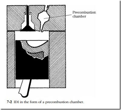
The precombustion chamber was first used on the Hornsby-Ackroyd low- compression oil engine and subsequently by Caterpillar, Deutz, and Mercedes-Benz, and other diesel manufacturers (Fig. 7-2). The precombustion chamber, also known as a hot bulb because of its shape and absence of any provision for cooling, occupies 25–40% of the total swept volume.
As the piston approaches tdc, the injector opens to send a solid stream of fuel into the hot bulb. The charge ignites, bulb pressure rises, and a stream of burning fuel jets through the connecting channel and into the main chamber, where there is sufficient air to complete combustion. The smaller the channel, the greater the acceleration and, all things equal, the more complete the fuel-air mixing. These chambers employ pintle-type injectors.
Swirl chamber
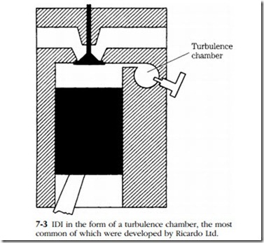
The swirl, or turbulence, chamber is similar in appearance to the precombustion chamber, but functions differently (Fig. 7-3). During compression, the disc-shaped or spherical antechamber imparts a circular motion to the air, which accelerates as the piston approaches tdc. The injector is timed to open at the peak of vortex speed. As the piston rounds tdc, combustion-induced pressure in the antechamber reverses the flow. A turbulent stream of burning fuel and superheated air exits the antechamber and rebounds off the piston to saturate the main chamber.
The swirl chamber was invented by Sir Harry Ricardo during the late 1920s and underwent numerous alterations during its long career. Except for Mercedes-Benz, most diesel cars and light commercial vehicles of the postwar era and for many years after employed the Ricardo Comet V chamber. These chambers are more economical than hot-bulb chambers, but are noisier.
The 6.25L engine used by General Motors for pickup trucks during the 1980s and early 90s demonstrates the tradeoffs implicit in combustion-chamber design. While the Ricardo chamber depends upon swirl for mixing, velocity is also important. Initially, these GM engines were set up with a small-diameter port between the main and swirl chambers. The pressure drop across the port generated velocity that, in conjunction with swirl, resulted in good air-fuel mixing and fuel economy. Near the end of the production run, GM acquiesced to customer demands for more power by enlarging the connecting port. More fuel could be passed, but thermal efficiency suffered. Fuel economy, which had approached 20 miles/gal, dropped to 14 or 15 mpg.
Energy cell
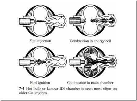
Examples of the energy cell, or Lanova divided chamber, can still be encountered in vintage Caterpillar tractor engines (Fig. 7-4). The cell consists of a kidney- shaped main chamber, located over the piston, and a secondary chamber, or energy
cell, which is divided into two parts. The cell opens to a narrow throat, situated between the two lobes of the main chamber.
During the compression stroke about 10% of the air volume passes into the energy cell. The injector, mounted on the far side of the main chamber, delivers a solid jet of fuel aimed at the cell. A small percentage of the fuel shears off and remains in the main chamber and some collects in the cell chamber closest to the piston bore. But most of the fuel dead-ends in the outermost cell chamber. .
Ignition occurs in this outer chamber. Unburned fuel and hot gases accelerate as they pass through the venturi between the two cell chambers and enter the main chamber. The rounded walls of the main chamber impart a swirl to the charge to promote better mixing.


