Capacitor Failure Modes
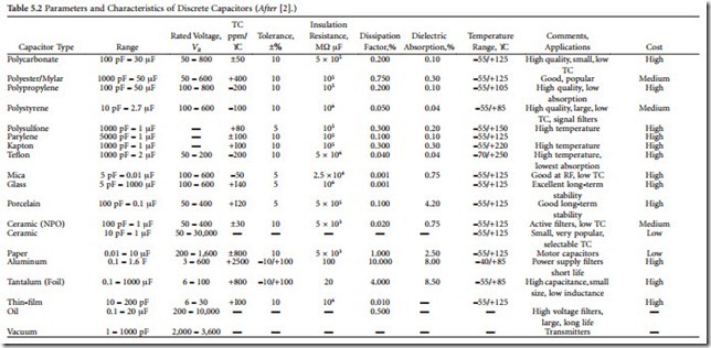
Experience has shown that capacitor failures are second only to semiconductors and vacuum tubes in components prone to malfunction in electronic equipment. Capacitors for ac applications range from high-voltage oil-filled devices, such as the one shown in Figure 5.5, to low voltage, high capacitance devices of the type typically found in power supplies (both linear and switching). Of all the various types of capacitors used today, it is estimated that electrolytics present the greatest potential for problems to equipment users.
Electrolytic Capacitors
Electrolytic capacitors are popular because they offer a large amount of capacitance in a small physical size. They are widely used as filters in low-voltage power supplies and as coupling devices in audio and RF stages. An aluminum electrolytic capacitor consists of two aluminum foil plates separated by a porous strip of paper (or other material) soaked with a conductive electrolyte solution. Construction of a typical device is illustrated in Figure 5.6. The separating material between the capacitor plates does not form the dielectric but, instead, serves as a spacer to prevent the plates from mechanically short-circuiting. The dielectric consists of a thin layer of aluminum oxide that is electrochemically formed on the positive foil plate. The electrolyte conducts the charge applied to the capacitor from the negative plate, through the paper spacer, and into direct contact with the dielectric. This sandwich arrangement of foil-spacer-foil is then rolled up and encapsulated.
Problems with electrolytic capacitors fall into two basic categories: mechanical failure and failure of electrolyte.
Mechanical Failure
Mechanical failures relate to poor bonding of the leads to the outside world, contamination during manufacture, and shock-induced short-circuiting of the aluminum foil plates. Typical failure modes include short circuits caused by foil impurities, manufacturing defects (such as burrs on the foil edges or tab connections), breaks or tears in the foil, and breaks or tears in the separator paper.
Short circuits are the most frequent failure mode during the useful life period of an electrolytic capacitor. Such failures are the result of random breakdown of the dielectric oxide film under normal stress. Proper capacitor design and processing will minimize such failures. Short circuits also can be caused by excessive stress, where voltage, temperature, or ripple conditions exceed speci- fied maximum levels.
Open circuits, although infrequent during normal life, can be caused by failure of the internal connections joining the capacitor terminals to the aluminum foil. Mechanical connections can develop an oxide film at the contact interface, increasing contact resistance and even-
tually producing an open circuit. Defective weld connections also can cause open circuits. Excessive mechanical stress will accelerate weld-related failures.
Temperature Cycling
Capacitors are subject to failures induced by thermal cycling. Experience has shown that thermal stress is a major contributor to failure in aluminum electro- lytic capacitors. Dimensional changes between plas- tic and metal materials can result in microscopic ruptures at termination joints, possible electrode oxidation, and unstable device termination (changing series resistance). The highest-quality capacitor will fail if its voltage or current ratings are exceeded. Appreciable heat rise (20°C during a 2-hour period of applied sinusoidal voltage) is considered abnor- mal and may be a sign of incorrect application of the component or impending failure of the device.
temperature on capacitor life. Note that operation at 33% duty cycle is rated at 10 years when the ambient temperature is 35°C, but the life expectancy drops to just 4 years when the same device is operated at Paper soaked in electrolyte 55°C. A common rule of thumb is this: Within the range of + 75°C through the full-rated temperature, stress and failure rates double for each 10°C increase in operating temperature. Conversely, the failure rate is reduced by half for every 10°C decrease in operating temperature.
Electrolyte Failures
Failure of the electrolyte can be the result of application of a reverse bias to the component or of a drying of the electrolyte itself. Electrolyte vapor transmission through the end seals occurs on a continuous basis throughout the useful life of the capacitor. This loss has no appreciable effect on reliability during the useful life period of the product cycle. When the electrolyte loss approaches 40% of the initial electrolyte content of the capacitor, however, the electrical parameters deteriorate and the capacitor is considered to be worn out.
As a capacitor dries out, three failure modes may be experienced: leakage, a downward change in value, or dielectric absorption. Any one of these can cause a system to operate out of tolerance or fail altogether.
The most severe failure mode for an electrolytic is increased leakage, illustrated in Figure 5.8. Leakage can cause loading of the power supply or upset the dc bias of an amplifier. Loading of a supply line often causes addi- tional current to flow through the capacitor, possibly resulting in dangerous overheating and catastrophic fail- ure.
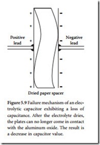
A change of device operating value has a less devas- tating effect on system performance. An aluminum elec- trolytic has a typical tolerance range of about ± 20%. A capacitor suffering from drying of the electrolyte can experience a drastic drop in value (to just 50% of its rated value, or less). The reason for this phenomenon is that after the electrolyte has dried to an appreciable extent, the charge on the negative foil plate has no way of coming in contact with the aluminum-oxide dielectric. This failure Paper soaked in electrolyte
Aluminum
mode is illustrated in Figure 5.9. Remember, it is the alu- minum-oxide layer on the positive plate that gives the electrolytic capacitor its large rating. The dried-out paper spacer, in effect, becomes a second dielectric, which signif- icantly reduces the capacitance of the device.
oxide dielectric
Capacitor Life Span
The life expectancy of a capacitor — operating in an ideal circuit and environment — will vary greatly, depending upon the grade of device selected. Typical operating life, according to capacitor manufacturer data sheets, range from a low of 3 to 5 years for inexpensive electrolytic devices, to a high of greater than 10 years for computer- grade products. Catastrophic failures aside, expected life is a function of the rate of electrolyte loss by means of vapor transmission through the end seals, and the operating or storage temperature. Properly matching the capacitor to the application is a key component in extending the life of an electrolytic capacitor. The primary operating parame- ters include:
• Rated voltage — the sum of the dc voltage and peak ac voltage that can be applied continuously to the capacitor. Derating of the applied voltage will decrease the failure rate of the device.
• Ripple current — the rms value of the maximum allowable ac current, specified by product type at 120 Hz and +85°C (unless otherwise noted). The ripple current may be increased when the component is operated at higher frequencies or lower ambient temperatures.
Dried paper spacer
• Reverse voltage — the maximum voltage that can be applied to an electrolytic capacitor without damage. Electrolytic capacitors are polarized and must be used accordingly.
Tantalum Capacitor
Tantalum electrolytic capacitors have become the preferred type of device where high reliability and long service life are primary considerations. The tantalum pentoxide compound possesses high dielectric strength and a high dielectric constant. As the components are being manufactured, a film of tantalum pentoxide is applied to the electrodes by means of an electrolytic process. The film is applied in various thicknesses. Figure 5.10 shows the internal construction of a typical tantalum capacitor. Because of the superior properties of tantalum pentoxide, tantalum capacitors tend to have as much as three times higher capacitance per volume efficiency as an aluminum electrolytic capacitor. This, coupled with the fact that extremely thin films can be deposited during the electrolytic process, makes tantalum capacitors efficient with respect to the number of microfarads per unit volume.
The capacitance of any device is determined by the surface area of the conducting plates, the distance between the plates, and the dielectric constant of the insulating material between the plates. In the tantalum capacitor, the distance between the plates is small; it is just the thickness of the tantalum pentoxide film. Tantalum capacitors contain either liquid or solid electrolytes.


