Neutral Point Potential Control Method
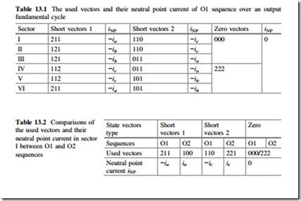
Regarding the Neutral Point (NP) potential, sequence O1 utilizes the short vectors which have zero accumulated NP current iNP over a fundamental cycle, as summarized in Table 13.1. Therefore, the positive and negative DC bus can naturally be balanced without any active methods. However, under some nonideal conditions (e.g., unbalance loads or power devices), the active NP potential control method for the normal SVM sequence cannot be applied, because only one type of short vectors with negative NP current are used and no redundant short vectors are included in the optimized sequence O1.
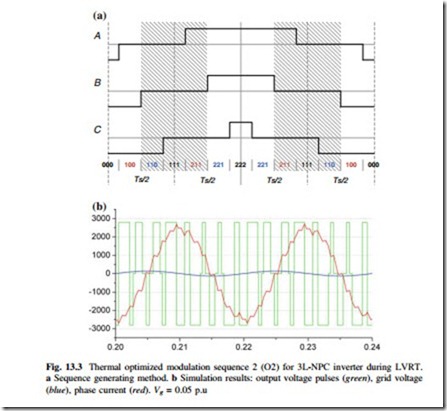
A solution to this problem is to generate another compensating vector sequences with the same zero vectors 000, 222, but the other pair of redundant short vectors with positive NP current. The new compensating sequence, which is called O2 here, has the opposite impact on the direction and amplitude of iNP compared to the O1 sequence, as compared in Table 13.2, in which only sector I are indicated for the simplicity. The generation of the compensating sequence O2 is shown in Fig. 13.3a. The simulation results of the compensating sequence O2 is shown in Fig. 13.3b, and it can be seen that when the phase current achieves its maximum value, the 3L-NPC inverter output only two voltage levels between positive and negative voltage level for 60° (in Fig. 13.3a zero voltage level for B phase is eliminated). This feature will contribute to the loss reduction in the NPC diodes, because there is no current conducting or switching in the NPC diodes during these periods when the 3L-NPC inverter eliminate zero output voltage level. Therefore, sequence O2 can be considered as a thermal optimized sequence for the 3L-NPC inverter during
LVRT, and also it can compensate the neutral point current of optimized sequence O1.
It can be seen that both of the sequences O1 and O2 start and end with zero vector 000, and thereby they can be alternated in the neighboring carrier cycles to enable the NP potential control ability without any extra switching processes. Because both of the short vectors which disturb the NP potential in sequence O1 or O2 will be compensated in the next carrier cycle, it is expected that the NP potential control ability by alternating the O1 and O2 sequence will be better than the normal sequence, in which only one short vector can be compensated in a switching cycle.
It is noticed that, the equivalent switching frequency is also doubled by the optimized modulation sequence O2, the carrier frequency thereby needs to be adjusted to half in order to acquire the same switching frequency as the normal SVM sequence.

