Wave shaping Circuits
An RC network can change the shape of complex waveforms so that the output barely resembles the input. The amount of distortion is determined by the RC time constant. The type of distortion is determined by the component the output is taken across. If the output is taken across the resistor, the circuit is called a differentiator. A differentiator is used to produce a pip or peaked waveform from square or rectangular waveforms for timing or synchronizing circuits. It is also used to produce trigger or marker pulses. If the output is taken across the capacitor, the circuit is called an integrator. An integrator is used for waveshaping in radio, television, radar, and computers.
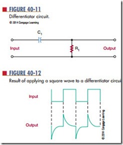
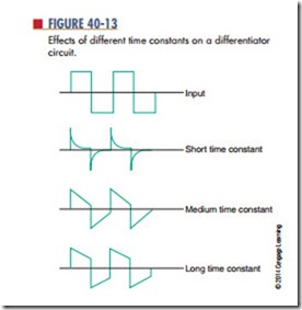
Figure 40-11 shows a differentiator circuit. Recall that complex waveforms are made of the fundamental frequency plus a large number of harmonics. When a complex waveform is applied to a differentiator, each frequency is affected differently. The ratio of the capacitive reactance (XC) to R is different for each harmonic. This results in each harmonic being shifted in phase and reduced in amplitude by a different amount. The net result is distortion of the original waveform. Figure 40-12 shows what happens to a square wave applied to a differentiator. Figure 40-13 shows the effects of different RC time constants.
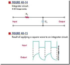
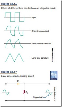
An integrator circuit is similar to a differentiator except that the output is taken across the capacitor (Figure 40-14). Figure 40-15 shows the result of applying a square wave to an integrator. The integrator changes the waveform in a different way than the differentiator. Figure 40-16 shows the effects of different RC time constants.
Another type of circuit that can change the shape of a waveform is a clipping circuit, or limiter circuit (Figure 40-17). A clipping circuit can be used to
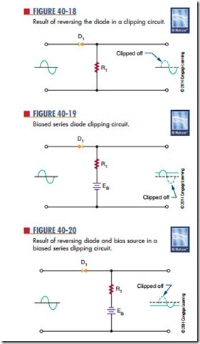
square off the peaks of an applied signal, obtain a rectangular waveform from a sine-wave signal, eliminate positive or negative portions of a waveform, or keep an input amplitude at a constant level. The diode is forward biased and conducts during the positive portion of the input signal. During the negative portion of the input signal, the diode is reverse biased and does not conduct. Figure 40-18 shows the effect of reversing the diode: The positive portion of the input result of applying a square wave to an integrator circuit.
By using a bias voltage, the amount of signal that is clipped off can be regulated. Figure 40-19 shows a biased series clipping circuit. The diode cannot con- duct until the input signal exceeds the bias source. Figure 40-20 shows the result of reversing the diode and the bias source.
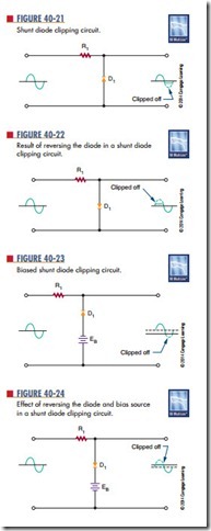
A shunt clipping circuit performs the same func- tion as the series clipper (Figure 40-21). The difference is that the output is taken across the diode. This cir- cuit clips off the negative portion of the input signal. Figure 40-22 shows the effect of reversing the diode. A shunt clipper can also be biased to change the clipping level, as shown in Figure 40-23 and Figure 40-24.
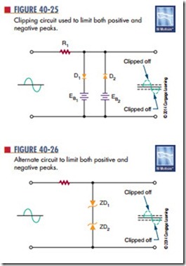
If both the positive and the negative peaks must be limited, two biased diodes are used (Figure 40-25). This prevents the output signal from exceeding predetermined values for both peaks. With the elimination of both peaks, the remaining signal is generally square
shaped. Therefore, this circuit is often referred to as a square-wave generator.
Figure 40-26 shows another clipping circuit that limits both positive and negative peaks. Therefore, the output is clamped to the breakdown voltage of the zeners. Between the two extremes, neither zener di- ode will conduct, and the input signal is passed to the output.
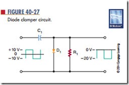
Sometimes it is desirable to change the DC refer- ence level of a waveform. The dC reference level is the starting point from which measurements are made. A clamping circuit can be used to clamp the top or bottom of the waveform to a given DC voltage. Unlike a clipper, or limiter, circuit, a clamping circuit does not change the shape of the waveform. A diode clamper (Figure 40-27) is also called a DC restorer. This circuit is commonly used in radar, television, telecommunications, and computers. In the circuit shown, a square wave is applied to an input signal. The purpose of the circuit is to clamp the top of the square wave to 0 volts, without changing the shape of the waveform.
Questions
1. Draw schematic diagrams of the following rC networks:
a. Differentiator
b. Integrator
2. What are the functions of integrator and differentiator circuits?
3. Draw schematic diagrams of the following circuits:
a. Clipper
b. Clamper
4. What are the functions of clipper and clamper circuits?
5. What are applications of the following circuits?
a. Differentiator
b. Integrator
c. Clipper
Clamper
Related posts:
Incoming search terms:
- wave shaping circuits
- Wave shaping circuit
- wave shaping ckt
- wave shaping and switching circuits
- application of wave shaping circuits
- types of wave shaping circuits
- applications of wave shaping circuits
- what is wave shaping circuit
- wave shaping in electronics
- necessity of wave shaping circuits
- wave shaping circuits (clipper & clamper)
- wave shaping circuits tutorial
- wave shaping in edc
- waveshaping circuit
- details for wave shaping circuit in hindi language
- wave shaping
- list different wave shaping circuits
- wave shaping circuit digram
- wave shaping circuits pdf
- waveshaping
- waveshaping ckts
- is pulse shaping circuits and wave shaping circuits same
- rc wave shaping circuit
- wave shaping circuits and what are theirneed
- application of wave shaping circuit
- waveshaping circuits
- what are the applications of wave shaping circuits
- electric RC wave shaping
- wave shaping cicuits
- waveshiping circuit
- list different wave
- wave shaping circuits and its types
- Disuss wave shaping and switching circuits in detail
- wave shaping concepts
- switching and wave shapping curcuit
- haw diode is used as cipper ? draw the circuit diagram and explain the working of positive clippers and baised clippers in hindi
- necessity of wave shaping
- Types of wave shaping circuit
- topics on wave shaping circuits
- wave shaping in electronic of clipping and clamping
- wawe shaping circuits objective
- clippers and clamper wave shaping method
- applications of an intergrated used in wave shaping
- clipper and clamper are examples for wave shaping circuit
- व्हाट इस वेव शेपिंग सर्किट इन हिंदी
- define wave shaping and its type
- concept of waveshaping
- application of wave sha
- clipping on wave shapping circuit
- clippers wave shaping
