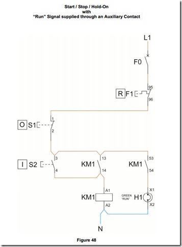
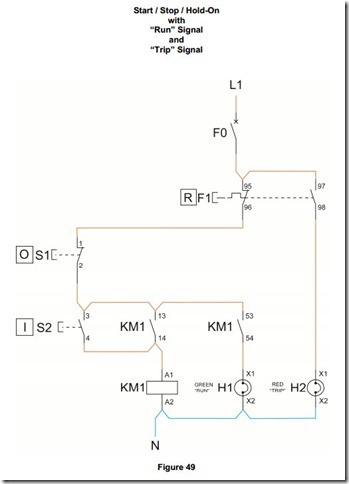
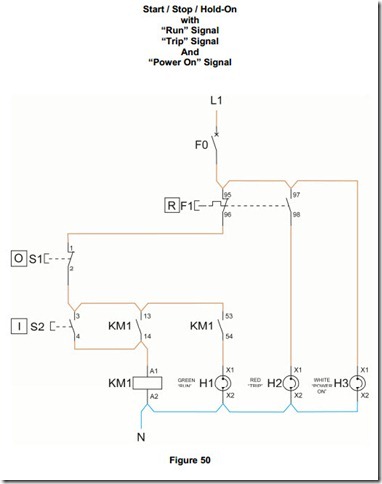
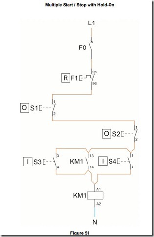
Motor Circuit Diagrams
Order of Use
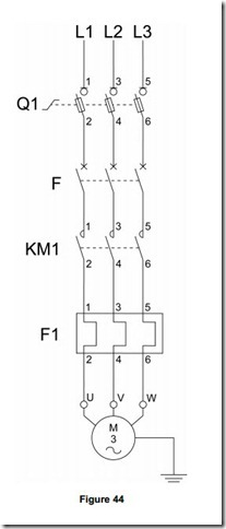
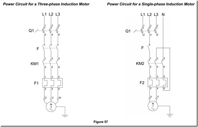
1. Install the Power Circuit for a Three Phase Induction Motor and connect out to a suitable three-phase induction motor.
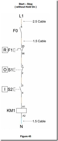
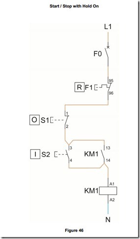
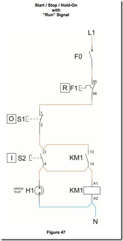
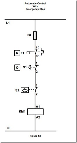
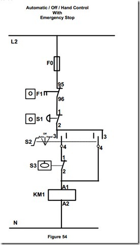
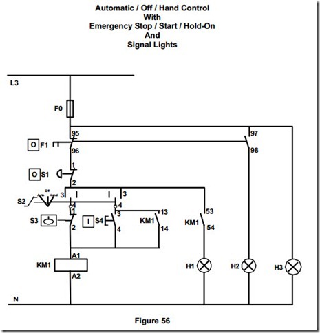
2. Install Control Circuits 1, 2 and 3, proving that each one is operating correctly.
3. Remove all control wiring ( this includes all neutral conductors involved ).
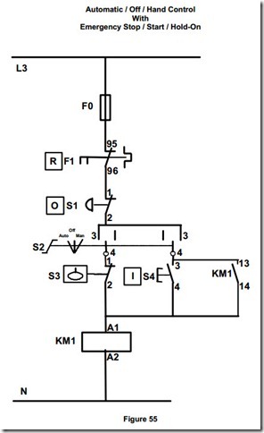
4. Install Control Circuits 4, 5 and 6, proving that each one is operating correctly.
5. Remove all control wiring.
6. Install Control Circuit 7 and prove that it is operating correctly.
7. Remove all wiring.
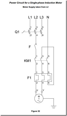
8. Install the Power Circuit for a Single Phase Induction Motor and connect out to a suitable single-phase induction motor.
9. Install Control Circuit 8 and prove that it is operating correctly.
10. Remove all control wiring.
11. Install Control Circuit 9 and prove that it is operating correctly.
12. Remove all control wiring.
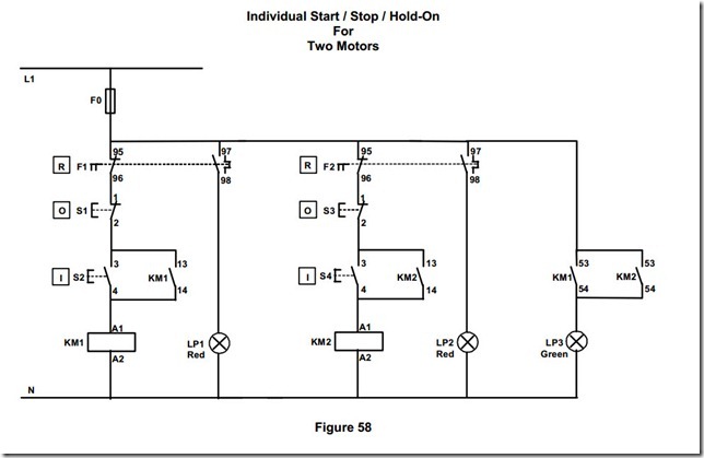
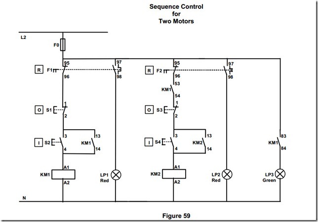
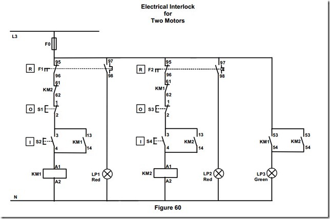
13. Install Control Circuits 10 and 11, proving that each one is operating correctly.
14. Remove all wiring.
15. Install the Power Circuit for a Three Phase and a Single Phase Induction Motor
16. Install Control Circuit 12 and prove that it is operating correctly.
17. Remove all control wiring.
18. Install Control Circuit 13 and prove that it is operating correctly.
19. Remove all control wiring.
20. Install Control Circuit 14 and prove that it is operating correctly.
