connecting Resistors in Parallel
A parallel circuit contains two or more resistors and provides two or more paths for current to flow. Each current path in a parallel circuit is called a branch. The current flows from the negative side of the voltage source, through each branch of the parallel circuit, to the positive side of the voltage source. If there is more than one path for current to flow between two points in a circuit with two or more resistors, the circuit is a parallel circuit.
The more resistors are connected in parallel, the less opposition there is to current flow. The less opposition there is to current flow, the lower the resistance in the circuit. In other words, when a resistor is added in parallel to a circuit, the total resistance in the circuit decreases because additional paths for current flow arebprovided. In a parallel circuit, the total resistance is always less than the resistance of any branch.
The total resistance in a parallel circuit is given by the formula:
Again, RT is the total resistance, R1, R2, and R3 are the individual (branch) resistors, and Rn is the number of the last resistor in the circuit.
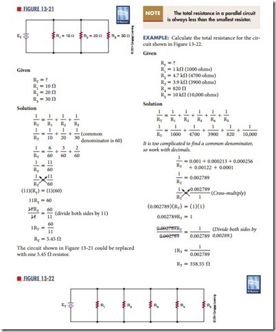
example: What is the total resistance of the circuit shown in Figure 13‑21?


