Nonsinusoidal Waveforms
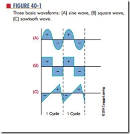
Figure 40-1 shows three basic waveforms that are rep- resented by the time domain concept. The three waveforms shown are sine wave, square wave, and sawtooth wave. Although the three waveforms are different, they all have the same period of frequency. By using various electronic circuits, these waveforms can be changed from one shape to another.
A periodic waveform is one with the same waveform for all cycles. According to the frequency domain concept, all periodic waveforms are made up of sine waves. In other words, superimposing a number of sine waves having different amplitudes, phases, and frequencies can form any periodic wave. Sine waves are important because they are the only waveform that cannot be distorted by RC, RL, or LC circuits.
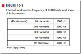
The sine wave with the same frequenc y as the periodic waveform is called the fundamental frequency. The fundamental frequency is also called the first harmonic. Harmonics are multiples of the fundamental frequency. The second harmonic is twice the fundamental, the third harmonic is three times the fundamental, and so on. Figure 40-2 shows the fundamental frequency of 1000 hertz and some of its harmonics. Harmonics can be combined in an infinite number of ways to produce any periodic waveform. The type and number of harmonics included in the periodic waveform depend on the shape of the waveform.
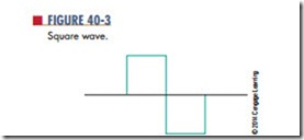
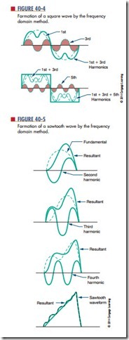
For example, Figure 40-3 shows a square wave. Figure 40-4 shows how a square wave is formed by the combination of the fundamental frequency with an infinite number of odd harmonics that cross the zero reference line in phase with the fundamental.
Figure 40-5 shows the formation of a sawtooth waveform. It consists of the fundamental frequency plus odd harmonics in-phase and even harmonics crossing the zero reference line 180º out of phase with the fundamental.
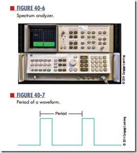
An oscilloscope displays waveforms in the time domain. A spectrum analyzer (Figure 40-6) displays waveforms in the frequency domain. Frequency domain analysis can be used to determine how a circuit affects a waveform.
Periodic waveforms are waveforms that occur at regular intervals. The period of a waveform is mea- sured from any point on one cycle to the same point on the next cycle (Figure 40-7).
The pulse width is the length of the pulse (Figure 40-8). The duty cycle is the ratio of the pulse width to the period. It can be represented as a percent- age indicating the amount of time that the pulse exists during each cycle.
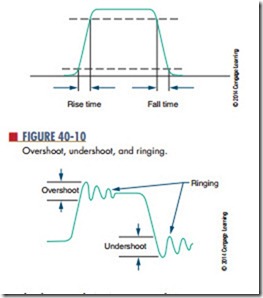
All pulses have rise and fall times. The rise time is the time it takes for the pulse to rise from 10% to 90% of its maximum amplitude. The fall time is the time it takes for a pulse to fall from 90% to 10% of its maximum amplitude (Figure 40-9). Overshoot,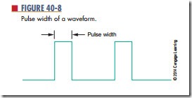
undershoot, and ringing are conditions common to high-frequency pulses (Figure 40-10).
overshoot occurs when the leading edge of a wave- form exceeds its normal maximum value. undershoot occurs when the trailing edge exceeds its normal mini- mum value. (The leading edge is the front edge of the waveform; the trailing edge is the back edge of the waveform.) Both conditions are followed by damped oscillations known as ringing. These conditions are undesirable but exist because of imperfect circuits.
Questions
1. Define the frequency domain concept.
2. How are the following waveforms constructed according to the frequency domain concept?
a. Square wave
b. Sawtooth wave
3. What is a periodic waveform?
4. What is a duty cycle?
5. Draw examples of overshoot, undershoot, and ringing as they apply to a waveform.
