Permanent magnet D.C motors:
These are same as that of ordinary D.C shunt motors, but the difference is they have permanent magnets instead of stationary field winding for producing the required magnetic flux.

The Figure 2.33 and 2.34 Shows the construction of a permanent magnet D.C motor. The magnetic frame or yoke supports the permanent magnet & also produces the return path for magnetic flux.
The armature consists of slot for windings, commutatorsegments& brushes are same as those in conventional D.C motors. The magnets are made of materials like ferrite, alnico, iron-cobalt, etc. These materials have high residual flux-density, & high energy output. These materials also have good mechanical properties.
Working & performance characteristics:

Figure 2.35
The equivalent circuit of a permanent magnet D.C motor is shown in Figure 2.35 Ra= Arm resistance; field windings are absent of permanent magnets.

Performancecharacteristics:

Torquev/s speed is almost linear. Therefore they are used in servo motors.
Efficiency is better than conventional motors. Therefore field losses are absent.
Because ofconstant flux, speed control is not possible with flux control method. Therefore only Armature control can be employed &hence the speeds obtained will be below the normal speeds.
Advantages:
1. No external Excitation is required to produce the flux. Therefore less losses & efficiency is high.
2. As field windings are absent, their size is smaller, cost decreases.
3. Motors designedupto 12V or less produce less TV & radio interference.
4. Less noise.
Disadvantages:
1. If the Armature reaction is more because of high armature current, permanent magnet may get demagnetized. Temperature may also affect the same.
2. The flux density produced in the air gap by the permanent magnet is limited.
3. Speeds above normal speeds are not possible.
Applications:
1. These motors normally run on 6V,12V, or 24V D.C supply.
2. They are extensively used in automobiles.
3. They are used in blowers, heaters & air conditions.
4. They are used for disc drives in personal computers.
5. They are used in fans, radio antennas, marine engine starters, wheel chairs & cordless power tools, vacuum chamber, mixer etc.
6. They are available upto a rating of 150KW.
PROBLEM:
(1) A permanent magnet D.C motor has resistance of 1Ω, the speed of the motor is 2000rpm when fed from 50V D.C source while taking 1.2A determine
(i) No load rotational losses.
(ii) The motor output when running at 1800rpm when source voltage is 48V.
(iii) Stalling torque when fed from 20V source.
SOLUTION:
Eb = V-Iara = 50 – 1.2 X1 = 48.8V
(i) At no load, no load losses = EbIa = (48.8) X (1.2) = 58.56 W.
(ii) Eb = Kp.ω, Kp = Eb/ω = 48.8/2π(2000/60)
= 0.2330V-S/rad.
For a speed of 1800rpm,
ω = 2πN/60 = 2π (1800)/60 = 188.49 rad/s. Therefore Eb= Kp.ω = (0.2330) (188.49) = 43.91V Ia = V -Eb/ra = 48 – 43.91/1 = 4.09A
Power developed = EbIa = (43.91) (4.09) = 179.59 W
Motor output = EbIa- Rotational losses = 179.59 – 58.56 = 121.03 W
(iii) Eb = 0 when motor stalls, V = Iara Therefore Ia = V/ra = 20/1 = 20A
Stall torque = KpIa = (0.2330) (20) = 4.66 N-m
Brushless DC Motor:
Construction of brushless DC motor:

Figure 2.37
The construction of brushless DC motor is shown in Figure 2.37.It consists of a stator and a permanent magnet rotor. The stator houses a polyphase winding in its slots. The rotor consists of permanent magnets. The stator windings are fed by an inverter. Rotor position sensors generate pulses for controlling the transistors in the inverter.
There are 2 types Brushless DC Motor
1. Unipolar or half wave Brushless DC Motor

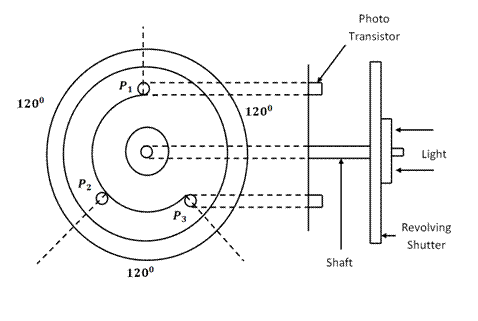
Figure 2.38
In this type, rotor consists of optical sensors. The optical sensor has a light source, three phototransistors P1, P2 and P3 mounted on the end plate of the motor separated by 1200 from each other and a revolving shutter coupled to the shaft of the motor. The optical sensor is shown in Figure 2.38. The stator, two pole rotor and driving circuit used to excite the stator winding are shown in Figure 2.39.
When the light falls on P1 it actuates the transistor Q1 and a pulse (Pl1) appears across Ph1 (phase 1) and creates a magnetic pole say North. The south pole of the rotor is attracted by this Ph1 and the rotor aligns with it. As the revolving shutter is coupled to shaft of the rotor, the light falls on P2 actuating transistor Q2 resulting in a pulse (Pl2) appearing across Ph2. This pulse creates a pole and the rotor is attracted by this Ph2. In this way, the rotor rotates in Uni-polar brushless DC motor.

2. Bipolar Brushless D Motor

Figure 2.41 shows the bipolar brushless DC motor. In the motors of higher ratings the inductive energy due to the windings will be high. This motor uses three phase inverter with feedback diodes to return the inductive energy to the supply. The rotor uses Hall effect sensors to sense the rotor position. The hall sensors are 1200 electrical from each other. Switching of each transistor occurs in response to rotor position sensor. Transistors are triggered in sequence. A pair of transistor conducts for 1200. Torque reversal is achieved by the shifting the base drive signal by 1200. This motor is suitable for high performance servo drives and also for ratings higher than 100 Watts.
Features of brushless DC motor:
i) Due to absence of brushless &commutator they require practically no maintenance.
ii) The operation is highly reliable and they have long life.
iii) They have low inertia & friction.
iv) Low radio frequency interference & hence the operation is noiseless.
v) Speeds upto 30000rpm & more is possible.
vi) Cooling is much better.
vii) Due to feed back diodes efficiency is high (75-80%).
Applications of brushless DC motor:
i) Unipolar brushless DC motor upto 100W, table driver, record players, spindle drives in H D drives, video recorders control systems.
ii) Also in aerospace, gyroscope & biomedical instruments.