Solid-State Control
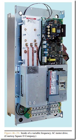
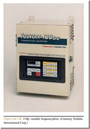
Most variable frequency drives operate by first changing the AC voltage into DC and then changing it back to AC at the desired frequency. A couple of variable frequency drives are shown in Figure 46 – 3A and Figure 46 – 3B. There are several methods used to change the DC volt- age back into AC. The method employed is generally determined by the manufacturer, age of the equipment, and the size motor the drive must control. Variable fre- quency drives intended to control the speed of motors up to 500 horsepower generally use transistors. In the circuit shown in Figure 46 – 4, a three-phase bridge rectifier changes the alternating current into direct current. The bridge rectifier uses six SCRs (Silicon Controlled Rectifiers). The SCRs permit the output voltage of the rectifier to be controlled. As the frequency decreases, the SCRs fire later in the cycle and lower the output volt- age to the transistors. A choke coil and capacitor bank are used to filter the output voltage before transistors Q1 through Q6 change the DC voltage back into AC. An electronic control unit is connected to the bases of tran- sistors Q1 through Q6. The control unit converts the DC voltage back into three-phase alternating current by turning transistors on or off at the proper time and in the proper sequence. Assume, for example, that transistors Q1 and Q4 are switched on at the same time. This permits stator winding T1 to be connected to a positive volt- age and T2 to be connected to a negative voltage. Cur- rent can flow through Q4 to T2, through the motor stator winding and through T1 to Q1.
Now assume that transistors Q1 and Q4 are switched off and transistors Q3 and Q6 are switched on. Current will now flow through Q6 to stator winding T3, through the motor to T2, and through Q3 to the positive of the power supply.
Since the transistors are turned completely on or completely off, the waveform produced is a square wave instead of a sine wave (Figure 46 – 5). Induction motors will operate on a square wave without a great deal of problem. Some manufacturers design units that will produce a stepped waveform as shown in Figure 46 – 6. The stepped waveform is used because it more closely approximates a sine wave.
Some Related Problems
The circuit illustrated in Figure 46 – 4 employs the use of SCRs in the power supply and junction transistors in the output stage. SCR power supplies control the output voltage by chopping the incoming waveform.
This can cause harmonics on the line that cause over- heating of transformers and motors, and can cause fuses to blow and circuit breakers to trip. When bipolar junction transistors are employed as switches, they are generally driven into saturation by supplying them with an excessive amount of base-emitter current. Saturating the transistor causes the collector-emitter voltage to drop to between 0.04 and 0.03 volts. This small voltage drop allows the transistor to control large amounts of current without being destroyed. When a junction transistor is driven into saturation, however, it cannot recover or turn off as quickly as normal. This greatly limits the frequency response of the transistor.

