Practical limitations of line-commutated converters
The above analysis covers the theoretical aspects of both uncontrolled and controlled converters. In practice, the components are not ideal and the commutations are not instantaneous. This results in certain deviations from the theoretical performance. One of the deviations is that the DC load current is never completely smooth.
Reasons
• Accepting that the instantaneous DC voltage VD can never be completely smooth, if the load is purely resistive, the DC load current cannot be completely smooth because it will linearly follow the DC voltage.
• Also, at delay angles α > 60º, the DC output voltage becomes discontinuous and, consequently, so would the DC current.
Remedy
In an effort to maintain a smooth DC current, practical converters usually have some inductance LD in series with the load on the DC side. For complete smoothing, the value of LD should theoretically be infinite, which is not practical.
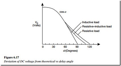
The practical consequence of this is that the theoretical formula for the calculated value of DC voltage (VD = 1.35 VRMS cos α) is not completely true for all values of the delay angle α. Practical measurements confirm that it only holds true for delay angles of up to 75º, but this depends on the load type and in particular, the DC load inductance. Experience shows that for a particular delay angle α > 60º, the average DC voltage will be higher than the theoretical value, as shown in the Figure 6.17.
Applications for line-commutated rectifiers
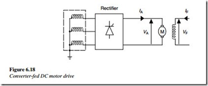
An important application of the line-commutated converter is the DC motor drive. Figure 6.18 shows a single controlled line-commutated converter connected to the armature of a DC motor. The converter provides a variable DC voltage VA to the armature of the motor. This is how the control circuit of the converter is used to change the motor speed.
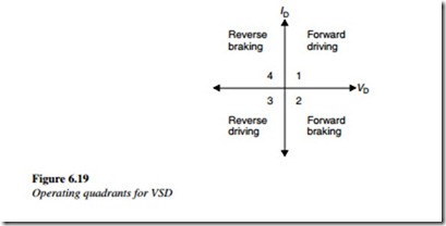
When the delay angle is less than 90º, the DC voltage is positive and a positive current IA flows into the armature of the DC motor, to deliver active power to the load. The drive system is said to be operating in the 1st quadrant (Figure 6.19), where the motor runs in the forward direction, with a transfer of active power from the supply to the motor and its mechanical load.
The motor field winding is separately excited from a simple diode rectifier and carries a field magnetizing current IF. For a fixed field current, the speed of the motor is proportional to the DC voltage at the armature. The speed can be controlled by varying the delay angle of the converter and its output armature voltage VA.
If the delay angle of the converter is increased to an angle greater than 90º, the voltage VD will become negative and the motor will slow to a standstill. The current ID also reduces to zero and the supply line can be disconnected from the motor without breaking any current.
Consequently, to stop a DC motor, the delay angle must be increased to a value sufficiently larger than 90º to ensure that the voltage VD becomes negative. With VD negative and ID still positive, the converter transiently behaves like a generator and produces a braking torque.
In addition, this acts as a brake to slow the motor and its load quickly to a standstill. In this situation, the drive system is said to be operating in the 2nd quadrant where the motor is running in the forward direction. The converters discussed so far have been single converters, which can only operate with a positive DC current (ID = +ve), which means that the motor can only run in the forward direction but an active power can be transferred in either direction. Single DC converters can only operate in quadrants 1 and 4 and are known as second quadrant converters.


