6 ·10 DEVELOPMENT OF CIRCUIT 9
This circuit will be a magnetic control for a wound-rotor motor. The customer desires four steps of automatic definite-time ac celeration when the RUN button is pressed. He also desires the option of running the motor at any one of the four reduced speeds by pressing a push button for that speed. He also wishes to be able to change speeds at will, either up or down, after the motor has accelerated to run speed.
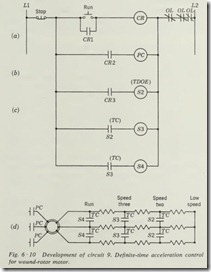
In order to visualize what contacts and control relays will be needed, an elementary drawing of the secondary circuit for the motor should be considered (Fig. 6·10d). This circuit pro vides the essentials of a four-step acceleration or four indepen dent speeds, provided the contacts are properly controlled. To provide definite-time control, these contacts would be time clos ing (TC).
The first step in development of this circuit would be to provide the four-step definite-time acceleration, using a RUN button to initiate the control process. Figure 6 ·10a shows our circuit as it is developed. The provision of definite-time acceleration requires the use of time-delay relays for each speed. A control relay with three-wire control seems required for the run condition.
When the RUN button is pressed , the circuit is complete to the coil of CR, thus closing CR 1 to maintain the circuit. Contact CR2 closes and energizes the primary contactor PC, thus energiz ing the primary of the motor. Some form of interlock should be provided to prevent the motor from starting unless all the resistance is in the secondary circuit, speed 1; however, this can best be provided after the balance of the speed control is developed.
A third contact on the control relay (CR) (Fig. 6 ·10b), CR3, can be used to energize a time-delay-on-energizing ( TDOE) relay S2 which has two TC contacts connected to short out
the first section of the resistance grid (Fig. 6 ·10d), thus provid ing acceleration to the second step when S2 times out.
To provide the third step of acceleration (Fig. 6 ·10c), it is obvious that a second TC contact on S2 will be required to energize a second TDOE relay S3 which has two TC contacts connected to short out the second section of the resistance grid (Fig. 6 ·10d) . The fourth step of acceleration is provided by a similar circuit.
The circuit of Fig. 6 ·10c provides a satisfactory degree of interlock in that the contacts of S2, S3, and S4 open whenever the STOP button is pressed and restore all resistance to the secon
dary circuit of the motor. This circuit satisfies the first specifica tion for the circuit development.
The second specification for independent speed control after acceleration will require some modification of the circuit of Fig. 6 ·10d. To be able to select any speed at will, the operator must be able to open any closed contacts and close any open contacts in the secondary circuit as required for that speed.
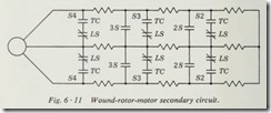
Adding a normally closed contact in series with each TC contact in the circuit of Fig. 6 ·10d would allow the equivalent of opening any closed contacts in the secondary circuit.
Adding a normally open contact in parallel with each group of two series contacts would provide the effect of closing any open contacts in the secondary circuit. These contacts are shown in Fig. 6 ·11.
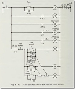
Figure 6 ·12 provides push-button control of the added con tacts of Fig. 6 ·11 and satisfies the second specification for the circuit. A time closing contact on S4 should be used in a stop function for the push buttons to assure that the motor has accel erated to run speed before it can be operated at a lower speed.
The low-speed push button energizes a relay LS in a three wire control circuit. Six normally closed contacts on LS are connected in series with the TC contacts in the circuit of Fig. 6 ·11. When the low-speed button is pressed, relay LS is ener gized and opens all six normally closed contacts, which restores all resistance in the secondary circuit and results in low-speed operation.
To increase speed from low or first speed to second speed, relay 2S must be added in a three-wire circuit with a normally open push button. One normally open contact 2S is used to seal in LS when moving up in speed and to energize LS when moving down from run to second speed. Two normally open contacts on 2S are used to short out part of the resistance grids (Fig. 6 ·11).
The third speed is added by duplicating the second speed components using contacts indicated by 3S on the circuits of Figs. 6 ·11 and 6 ·12. There is no need for interlock when going from second speed to third speed because the contacts 2S in Fig. 6 ·11 do not affect the operation even though they remain closed.
The fourth or run speed can be restored by merely dropping out any and all instantaneous contact<; and relays associated · with the lower speeds, since all TC contacts in Fig. 6 ·11 are now closed. This can be done by adding a normally closed push button as indicated in Fig. 6 ·12.
The circuit as developed up to this point would work as long as the operator always wanted to go from a low speed to a higher speed. To reduce the speed, it is necessary to open the contacts 2S and 3S of Fig. 6 ·11. Interlocking by the use of contacts could involve more relays in the circuit, but normally closed contacts as part of the speed-control push buttons, as indicated in Fig . 6 ·12, provide positive drop out of all higher speeds whenever a lower speed is desired.
This circuit may seem slightly impractical in its requirements, but is used to indicate that any requirements of the system can be met by a systematic development.
6 ·11 DEVELOPMENT OF CIRCUIT 10
The requirements for this circuit are to develop a control system which will provide definite-time speed control for a d-e shunt motor. The owner wishes to be able to start the motor and have
it accelerate to any one of five preselected speeds. Speeds 1 and 2 are below base speed (underspeed control) . Speed 3 is base speed, and speeds 4 and 5 are above base speed (overspeed control).
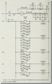
The requirement of two speeds below base speed indicates three resistance grids in series with the armature (Fig. 6 ·13a). One of the resistances would be short-circuited for speed 1, the second for speed 2, and the third for base speed by contacts S1a, S2a, and S3a.
The requirement of two speeds above base speed indicates two resistance grids in series with the shunt field and shorted out by normally closed contacts S4a and S5a until base speed has been reached and overspeed is required.
The addition of an overload heating element and line contacts completes the motor circuit. This leaves only the development of the control circuit to activate the contacts properly.
Step 1 in the development of the control circuit would be to provide for speed 1 by connecting a push button to energize the first TDOE relay Sl. This circuit must remain energized; therefore, it requires a three-wire control.
When a d-e motor is started, considerable resistance is required in the armature circuit until it begins to accelerate. This requires a time delay before R 1 is shorted out. If contact Sla is a time closing contact, it will provide time for the motor to reach the desired speed.
The line contacts must be closed before any current can flow through the motor circuit. If the line contact is an instantaneous contact on Sl, this requirement will be met. An overload contact and STOP button must be provided to protect and stop the motor. Contact S1c, used to maintain the circuit to coil Sl, must be an instantaneous closing contact on Sl.
At this point it is obvious that Sl must be energized regardless of the speed selected; therefore, we can add a maintaining con tact for each speed in parallel with Slc. All these contacts must be of the instantaneous closing type.
The circuit of Fig. 6 ·l3b will start the motor and allow it
to accelerate to the desired speed, at which time Sla times out and removes R 1 from the circuit. The motor will run at this speed unless other buttons are pressed.
The requirement of a push button for each speed indicates a three-wire circuit and a TDOE relay for each speed. Figure 6 ·13c is a three-wire circuit to energize and maintain S2. The instantaneous contact S2c will energize Sl and thereby close the line contact Slb. The relay S2 must provide a time delay twice as long as that of Sl so that Sl may time out and allow acceleration time for speed 2. Instantaneous contacts must be provided parallel to S2b in order to bring in speed 2 whenever a highet.speed is selected.
The other speeds are controlled by circuits similar to the one for speed 2. Each higher speed must have a longer setting on the time-delay relay and provide contacts to energize all lower speeds.
There are other circuits which could provide this control; however, this was chosen to illustrate the degree to which a circuit can be dependent upon proper interlocking.
6 · 12 DEVELOPMENT OF CIRCUIT 11
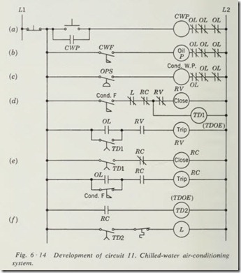
This circuit will be one for a chilled-water air-conditioning sys tem. The compressor is a 500-hp squirrel-cage motor driving a centrifugal compressor. Head pressure is controlled by con denser water furnished by a condenser-water pump. The chilled water is pumped to the heat exchanger by a chilled-water pump . . Protective control must be provided to shut down the compressor whenever flow ceases in either the chilled water or condenser water.
The starter for the compressor is a reduced-voltage autotrans former type using air circuit breakers requiring that a coil be energized to close the breaker and a second coil be energized to trip the breaker. Definite-time control of reduced-volt age starting is provided by a TDOE relay in the starter.
The first step in the system is to establish chilled-water flow and to sense by means of a flow switch that there actually is flow in the pipe. The flow switch (CWF) is usually located in the return water line to assure that flow is complete around the system. Figure 6 ·14a provides the START and STOP buttons for the system and energizes the chilled-water pump .
When chilled-water flow is sensed by the flow switch, the oil pump on the compressor must be energized and correct pres sure established (Fig. 6 ·14b). Once the oil-pressure switch senses sufficient pressure, it must energize the condenser-water pump (Fig. 6·14c) to provide cooling for the compressor and keep the head pressure from rising to a dangerous value.
The compressor has chilled-water flow, oil pressure, and condenser-water flow and is ready to be started under reduced volt age if the unloader assures that the load is less than 10 percent. There are many unloaders and vane positioners used. We shall indicate the unloaders as a contact L which is normally closed when the load is 10 percent or less. The unloader contact L should not allow the compressor to start if it is open. Figure 6 ·14d is the circuit for the reduced-voltage contactor closing coil ( RV). Remember that this contactor is latched closed; there fore the coil must be energized only briefly.
The trip coil on the breaker must be energized if an overload occurs during reduced-voltage start and when the run contactor is energized by the time-delay relay. The trip coil must be ener gized only momentarily; therefore, a contact on RV must remove the coil from the line. The trip-coil circuit must be held open when the run contactor is closed; therefore, normally open (N.0.) contact R V is connected in series with this circuit.
When the reduced-voltage start timer TDl times out, it closes its contacts to trip the reduced-voltage contactor and briefly en ergize the run-contactor closing coil (RC). The run contactor is now latched closed (Fig. 6 ·14e).
Protective control for the compressor while running must be paralleled normally open contacts in the trip-coil circuit. The chilled-water flow contact and the oil-pressure switch ( OPS) contact will cause a shutdown of the condenser-water · pump. The condenser-water flow contacts (Cond. F) in the start circuit will not shut down the compressor when they open; therefore, a set of contacts on this switch needs to be connected in the trip circuit of the run contactor for protection. These contacts would be normally closed when there is no flow, so that they will be open when flow is established. Normally open contact RC on the run contactor prevents the energizing of the trip coil unless the run contactor is closed.
All the circuit lacks at this point is the energizing of the loader device L after a short time delay to assure that the compressor is completely up to speed. The thermostat can then control the load ofthe compressor (Fig. 6·14f).
Summary
This selection of the book has been devoted to presenting a method of developing control circuits. While the few circuits developed here do not in any way approach the limitless number of possible circuits that the student of control will find in actual practice, they should provide the basic principles necessary for the development of any control circuit.
Develop the circuit one function at a time, adding only the components necessary to perform that function. Analyze the circuit after each addition to see that it has not interfered with any previous operation and that it actually does perform the function intended, before proceeding with any further additions to the circuit. If you follow these simple rules, you should have no trouble in developing a circuit to perform any desired func tion. The greatest danger in developing control circuits is to try to draw a complete circuit at one time. Therefore, it cannot be overstressed that step-by-step development will lead to fewer hours spent in trying to find out why a circuit did not work after it was wired.
It is highly recommended that the student practice developing circuits of various types and checking them to see that they actually should operate when wired. If a setup of control compo nents is available to the student, he should at this stage of his study develop circuits of various types and then actually wire them and test them to see that they work. Should the circuit not operate as expected, a student should then troubleshoot this circuit and determine why it did not operate. If such a continua tion of the study of the development of circuits is possible, a student will have a great advantage over others who have not had this practice when he tries to apply these principles on the job to actual circuits.
The principles involved in the development of control circuits have been clearly set down in this section of the book, and all that is required to perfect this technique to a satisfactory degree is practice by the student. Your own desires as to your degree of proficiency will dictate how much additional time you spend on practicing the development of control circuits.
Develop circuits for the following:
Review Questions
1. A motor controlled by a three-wire start-stop station.
2. Add to the above circuit a second push button for starting the motor from a different location.
3. Add to the above circuit a limit switch to stop the motor.
4. A motor controlled by a three-wire push-button station.
When this motor stops, it starts a second motor which runs until stopped by pressing a STOP button.
5. Revise the circuit of question 4 so that the second motor runs for only 2 minutes and then stops automatically.
6. Three motors connected so that they are all started by one START button and interlocked so that if any one of them should fail to start, or should drop out, all will stop. The STOP button stops all motors.
7. Two pumps started and stopped one at a time by a pressure switch. Provide a manual switch to run the pumps alternately.
8. Add to the circuit of question 7 a second pressure switch to start the idle pump if the pressure continues to drop.
9. Replace the manual switch in the circuit of question 8 with a stepping relay to alternate the pumps automatically each time they start.
10. Replace the stepping relay in the circuit of question 9 with a time clock to alternate the pumps every 24 hours.
11. Four motors started in compelling sequence. Provide a 20-sec time delay between the starting of each motor.
12. Four motors started in selective sequence.
13. A three-speed motor with selective sequence starting. Pro vide control so that the speed may be reduced without press ing the STOP button . (HINT: This is similar to plugging without reversal of the motor.)
14. There are four exhaust-fan motors in a building . Each fan is also equipped with a thermostat known as a firestat. Should any one of the firestats, which have normally closed contacts, open from high heat, it will stop all fans.
