The line-commutated thyristor rectifier bridge
The output DC voltage and the operational sequence of the diode rectifier in Figure 6.9, is dependent on the continuous changes in the supply line voltages and is not dependent on any control circuit. Therefore, it is called an uncontrolled diode rectifier bridge because the DC voltage output is uncontrolled and is fixed at 1.35 × VRMS.
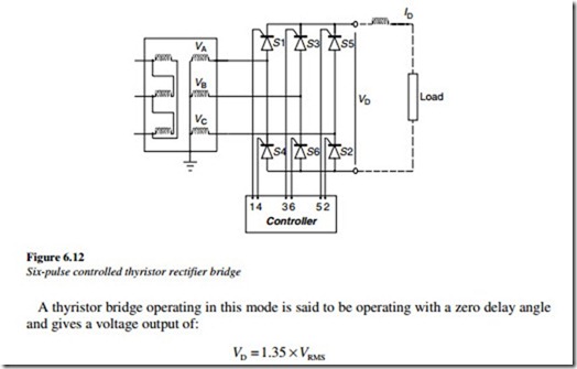
If the diodes are replaced with thyristors, it then becomes possible to control the point at which the thyristors are triggered and therefore, the magnitude of the DC output voltage can be controlled. This type of a converter is called a controlled thyristor rectifier bridge. This requires an additional control circuit, to trigger the thyristor, at the right instant. A typical six-pulse thyristor converter is shown in Figure 6.12.
Based on the previous chapter, the conditions required for a thyristor to conduct current
in a power electronic circuit are given below:
• A forward voltage must exist across the thyristor
• A positive pulse must be applied to the thyristor gate.
If each thyristor were triggered at the instant when the forward voltage across it tends to become positive, then the thyristor rectifier operates in the same way as the diode rectifier described above. All voltage and current waveforms of the diode bridge apply to the thyristor bridge.
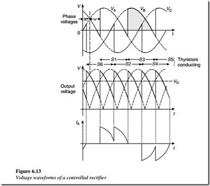
vThe output of the rectifier bridge can be controlled, by delaying the instant at which the thyristor receives a triggering pulse. This delay is usually measured in degrees, from the point at which the switch CAN turn on, due to the forward voltage becoming positive. The angle of delay is called the delay angle, or sometimes the firing angle, and is designated by the symbol α. The reference point, for the angle of delay, is the point where a phase voltage wave crosses the voltage of the previous phase and becomes positive, relative to it. A diode rectifier can be thought of as a converter with a delay angle of α = 0º. The main purpose of controlling a converter is to control the magnitude of the DC output voltage. In general, the larger the delay angle, the lower the average magnitude of the DC voltage. Under the steady state operation, of a controlled thyristor converter, the delay angle for each switch is the same. Figure 6.13 shows the voltage waveforms, where the triggering of the switches has been delayed by an angle of α degrees.
Operation
In the positive switch group, the positive DC terminal follows the voltage associated with the switch, which is in conduction in the sequence VA–VB–VC. Assume initially, that thyristor S1 associated with voltage VA is conducting and S3 is not yet triggered. The voltage on the positive bus on the DC side follows the declining voltage VA because, in the absence of an S3 conduction, there is still a forward voltage across S1 and it will continue to conduct.
When an S3 is triggered after a delay angle = α, the voltage on the positive bus jumps to VB, whose value it then starts to follow. At this instant, with both S1 and S3 conducting, a negative commutation voltage equal to VB–VA appears across the switch S1 for the commutation period, which then starts to turn off. With the passage of time, VB reaches its sinusoidal peak and starts to decline, followed by the positive DC terminal. Simultaneously, VC rises and when S5 is triggered, the same sequence of events is repeated and the current is commutated to S5.
As with the diode rectifier, the average magnitude of the DC voltage VD can be calculated, by integrating the voltage waveform over a 120º period, representing a repeating portion of the DC voltage. At a delay angle α, the DC voltage is given by the following equation:
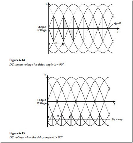
 This formula shows that the theoretical DC voltage output of the thyristor rectifier with a firing angle α = 0 is the same as that for a diode rectifier. It also shows that the average value of the DC voltage will decrease as the delay angle is increased and is dependant on the cosine of the delay angle. When α = 90º, then cos α = 0 and VD = 0, which means that the average value of the DC voltage is zero. The instantaneous value of the DC voltage is a saw-tooth voltage, as shown in Figure 6.14.
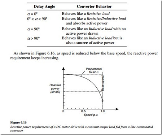
If the delay angle is further increased, the average value of the DC voltage becomes negative. In this mode of operation, the converter operates as an inverter. It is interesting to note that the direction of the DC current remains unchanged because the current can only flow through the switches in one direction. However, with a negative DC voltage, the direction of the power flow is reversed, and the power flows from the DC side to the AC side. A steady state operation, in this mode, is only possible, if there is a voltage source on the DC side. The instantaneous value of the DC voltage for α > 90º is shown in Figure 6.15. In practice, the commutation is not instantaneous and lasts for a period dependant on the circuit inductance and the magnitude of the commutation voltage. As in the idealized case, it is possible to estimate the commutation time, from the commutation circuit inductance and an estimate of the average commutation voltage.
As in the diode rectifier, the steady DC current ID comprises segments of current from each of the three phases on the AC side. On the AC side, the current in each phase comprises of non-sinusoidal blocks, similar to those associated with the diode rectifier and with similar harmonic consequences. In the case of the diode bridge, with a delay angle of α = 0, the angle between the phase current and the corresponding phase voltage on the AC side is approximately zero. Consequently, the power factor is unity and the converter behaves like a resistive load.
For the controlled rectifier, with a delay angle of α, the angle between the phase current and the corresponding phase voltage is also α, and called the power factor angleφ . This angle should be called the displacement factor because it does not really represent the power factor. Consequently, when the delay angle of the thyristor rectifier is changed to reduce the DC voltage, the angle between the phase current and voltage also changes by the same amount. The converter then behaves like a resistive-inductive load with a displacement factor of cosφ .
It is well known that the power factor associated with a controlled rectifier falls, when the DC output voltage is reduced.
A common example of this is a DC motor drive controlled by a thyristor converter. As the DC voltage is reduced, to reduce the DC motor speed, at a constant torque, the power factor drops and more reactive power is required at the supply line to the converter.


