Two-wire control
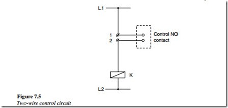
The circuit shown in Figure 7.5 can be used for an auto start operation of a motor after a power failure depending on the position of the control contact. The control contact may be a level switch contact or a temperature switch contact.
The contactor K remains energized as long as the control contact is in a close condition. If the power failure occurs, the motor turns off.
The motor will then restart automatically, once the power is restored since the control contact is in a close condition.
This circuit type is useful for pumps, fans, blowers, etc. where an automatic restarting of the device after a power failure is desirable depending on the control contact.
Three-wire control – start/stop
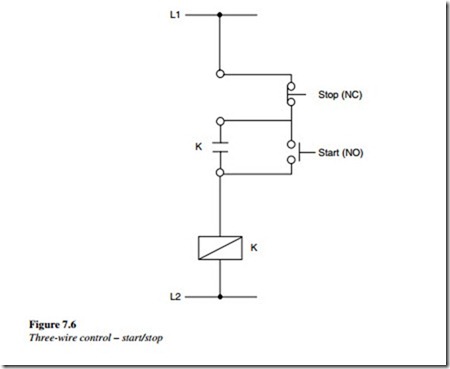
A three-wire control circuit for start/stop operation is shown in Figure 7.6. As shown in the diagram, NO contact of the start pushbutton and NC contact of the stop pushbutton are in series with the main contactor in the control circuit.
The main contactor K will energize as a start pushbutton is pressed and if the stop pushbutton is not pressed, it stays latched. The latching contact K is used for the main contactor.
If a power failure occurs and the motor stops, then the motor will not start automatically. Again, the start pushbutton has to be pressed to latch the main contactor
and to start the motor. This circuit type is useful in applications where the motor is not required to start automatically after a power failure so as to prevent the occurrence of a hazard to the surroundings.
Jog/inch circuits
Start/stop/jogging circuit using push buttons
If the machine has to perform small rotations, a control circuit is required to accomplish the ‘Inching’ motion of a motor.
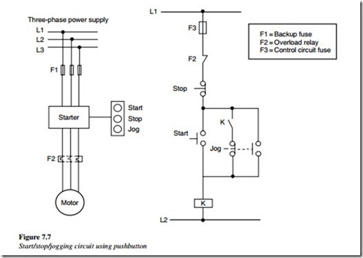
To serve the purpose, a ‘Jog/Inch’ control circuit for a three-phase motor is designed such that when the jog pushbutton is pressed, the motor runs and when the pushbutton is released the motor stops (Figure 7.7). Generally, this type of movement is used in machine tools.
Operation
As shown in the control circuit, a double-contact jog pushbutton is used with one NC contact and one NO contact. Therefore, when the jog button is pressed, the latching circuit to the starter coil (K) is opened by the NC contacts of the jog pushbutton. Therefore, the starter coil (K) will not lock in; rather it remains energized as long as the jog button is fully pressed. Thus, an ‘Inching/Jogging’ action can be achieved.
If the jog pushbutton were released suddenly, then if the NC contacts closes before the starter maintaining the contacts (K) open, the motor would continue to run. This in turn
can prove hazardous to the surrounding workers and machinery. A mechanical device can be installed which ensures that the starter-holding circuit is not reestablished if the jog button is released too rapidly.
Start/stop/jogging circuit using selector switch
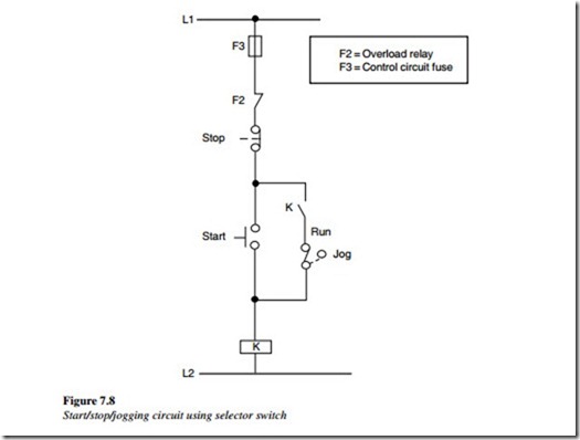
Figure 7.8 shows the use of a selector switch in the control circuit to obtain jogging. The start button performs twin functions; it works as a jog button as well as a start button.
To operate the motor in a run mode, the selector switch should be in the ‘RUN’ position. The K coil circuit is completed if the start button is pressed and it remains latched because of the latching contact K1 and the selector switch.
To operate the motor in the jog mode, the selector switch should be in the jog position. If the start button is pressed, the K coil circuit is completed but as soon as the start button is released, the K coil is de-energized because the latching circuit of K1 coil is open.


