MICROWAVE OVENS
Every era has contributed its own ideas and conveniences to the kitchen—from the open stove to the closed one, from wood to oil, coal, electricity and gas. And now the age of microwaves is here. Furthermore, microwave ovens were considered a luxury. For a long time, people considered that
microwave ovens were used for reheating food only. But as the pace of modern life has got faster and busier by the day, microwave cooking has proved extremely helpful in the efficient pre- paration of daily food, in the shortest possible time.
MICROWAVES
A microwave is a signal that has a wavelength of one foot (30.5 cm) or less. This converts to a frequency of 984 MHz, so all frequencies above 1000 MHz (1 GHz) are considered microwaves. The frequencies immediately below this border are considered ultra-high frequencies. The upper end of the microwave range contains the light frequencies, about 1015 Hz. However, because electronic transmission is so closely geared to half-wavelength devices, the practical upper limit is about 300 GHz, where one wavelength is about 0.04 inch (0.1 cm). Smaller devices are being made, but their power handling abilities are also micro.
Normally microwaves spread outwards as they travel through the atmosphere and disappear without effect. The microwave oven uses microwaves of frequency 2.4 GHz (12.5 cm wavelength) to cook food. Microwave ovens have a magnetron usually concealed in the roof of the oven, specifically designed to make use of the energy in the microwaves. Electricity applied to the magnetron tube is used to create microwave energy.
Microwaves enter the cooking area through openings inside the oven. A turntable or tray is located at the bottom of the oven. Microwaves cannot pass through the metal walls of the oven, but they can penetrate such materials as glass, porcelain and paper, the materials out of which microwave-safe cookware is constructed. Microwaves do not heat cookware, though cooking vessels will eventually get hot from the heat generated by the food.
4 concave reflectors are located on the left and back sides to concentrate the microwave energy on the food. In state-of-art microwave ovens, the wave reflector system (WRS) and dual-wave emission system (DES), Fig. 50.1, ensure that the food is always uniformly cooked.
Microwaves reflect off the metal components in the oven (such as the interior walls and the fine screen on the oven door). These metal parts prevent the escape of microwave energy. All microwave activity remains inside the oven. When the door is opened or the oven is switched off, the production of microwaves stops instantly.
TRANSIT TIME
Every electronic product with two or more terminals will have inter-electrodes capacitance across the terminals and inductance in series with the terminals. Both effects limit the usefullness of the device at high frequencies.
Values of 2 pF and 0.02 µH are typical interelectrode reactances that erode the high-frequency signals.
A second limitation is the time it takes for the electron to travel from one electrode to another electrode called the transit time. At microwave frequencies the time for one cycle of RF energy is often shorter than the transit time of the device. The measures required to improve one effect are the opposite of what is required to improve the other, and are therefore counter productive. For this reason the principle of using the transit time (as in magnetrons) instead of fighting it, has become basic to many of today’s microwave devices.
MAGNETRONS
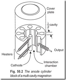
The word magnetron is a conjuction of the words magnet and electrons and identifies one of the major components, a very powerful magnet. The second major component is a cylindrical copper block, drilled and channeled as shown in Fig. 50.2. The centre opening is called theinteraction chamber. The holes drilled around the outer edge have a diameter equal to one- half wavelength at the operating frequency and are called resonant chambers. There will always be an even number of resonant chambers, usually not less than 6 and not more than 16.
With the magnetron used as a diode the copper block becomes the anode and a directly heated cathode is placed at the centre of the interaction space. The chamber is sealed with top and bottom cover plates and the air is drawn out to form a vacuum. The output connection is a wire loop in one of the
chambers that feeds to a coaxial cable fitting on the side wall of the block anode. Because the anode is exposed to the user it is placed at ground potential and the cathode is at a high negative potential. The magnetron will only operate as an oscillator (never as an amplifier) and finds its greatest use as a power oscillator.
The frequency of the magnetron will remain most stable when any one channel differs in phase from its immediate neighbouring channels by an exact multiple of π/4 radians. Best results are obtained at 4π/4 radians (π radians = 180°). This is called the π mode of operation. To ensure this phase shift of 180° alternate channels are strapped together as shown in Fig. 50.3.
WAVE GUIDES
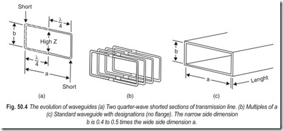
The part of a microwave system that established the theory of operation for all of the other devices is the interconnecting hardware called wave guide. The conductors of microwave energy constitute a departure from conventional cables in that they resemble a coaxial cable with the centre conductor removed, Fig. 50.4. Microwave energy is carried through the waveguide by reflection along its inside walls.
This is possible only if the guide is larger than one-half the length of the applied voltage wave. Thus the wave guide size is directly related to frequency. The waveguide factors that deserve attention are :
(a)attenuation losses per unit length
(b) size selection
(c) coupling methods
(d) guide impedance and
(e) power-handling ability
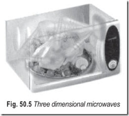
By transforming microwaves into 3D waves, the system ensures that every inch of food being cooked is immersed in 3D microwaves, resulting in food that is cooked more evenly.
Microwaves transformed into three dimensional waves come out of specially designed waveguides, Fig. 50.5.
MICROWAVE OVEN BLOCK DIAGRAM
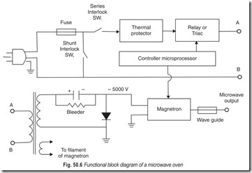
The block diagram of a microwave oven is given in Fig. 50.6. The mains plug and socket are three-pin earthing type. The fast blow ceramic fuse is of 15 A, 250 V. Interlock switches are linked with the oven door. Power will be applied to the mains transformer only when the oven door is closed. At least one interlock switch is in series with the transformer primary, hence even a spot of dirt in the relay or trial, cannot turn the oven on when the door is open.
There is yet another interlock across the power supply line. It normally remains open. If the door alignment is not correct it will be activated , putting a short circuit (crowbar) across the line and making the fuse to melt. Thus, the microwave oven is a fail safe device.
The voltage induced in the secondary winding is about 2000 V (rms) at 250 mA for normal domestic ovens. The transformer also has a tertiary winding for the magnetron filament. The high voltage return circuit is fastened directly to the chassis through the transformer frame. A half-wave doubler configuration is used for the rectifier, with a peak inverse voltage of about 12000 V. One end of the diode is connected to the chassis.
The bleeder capacitor (1 µF) should always be discharged before touching anything inside when the cover is removed. The high value bleeder resistor is slow to discharge; further it may be open.
The thermal protector is a PTC thermistor. The primary current decreases when the temperature rises abnormally. It senses the temperature of the magnetron as it is bolted to the magnetron case and is so connected electrically that its resistance comes in series with the primary circuit.
The controller is a microprocessor chip with a clock. It is activated by key-pad switches and sets the cooking time. It senses the temperature and moisture, sets the power levels and runs the display. There are three power levels. For HIGH the microwave generator remains on continuously; for MEDIUM it remains on for 10 seconds and off for 10 seconds; for LOW it remains on for 5 seconds and off for 15 seconds. The controller activates the microwave generator using either a relay or a triac.
LCD TIMER WITH ALARM
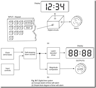
Most microwave ovens feature at least one timer with an alarm. Older appliances used mechanical timers, but modern microwave ovens and cooking ranges feature electronic timers using digital circuitry. The concept of a timer is sketched in Fig. 50.7. In this system, the keypad is the input and both the digital display and alarm buzzer are the output devices. The processing and storage of data occur within the digital circuits block in Fig. 50.7 (a).
A somewhat more detailed block diagram of a digital timer is shown in Fig. 50.7 (b). The digital circuits block has been subdivided into four blocks. They are the time-base clock, the self stopping down counter, the latch/decoder/driver, and the magnitude comparator. The input controls block presets the time held in the down counter. The time base is a stable multivibrator which generates a known frequency. In this case, the signal is a 1 Hz square wave. The accuracy of the entire timer depends on the accuracy of the time-base clock. Activating the start input control causes the down counter to decrement. Each lower number is latched and decoded by the latch/decoder/driver. This block also drives the display.
SINGLE-CHIP CONTROLLERS
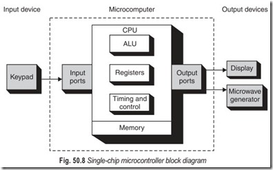
Most of us are familiar with general-purpose microcomputers such as the IBM PC and its clones and the Apple Macintosh, which are used in more than half of our homes and in almost all of our businesses. These microcomputers can perform a wide variety of tasks in a wide range of applications depending on the software (programs) they are running. There is a more specialised type of microcomputer call a microcontroller which is not a general-purpose computer. Rather, it is designed to be used as a dedicated or embedded controller which helps monitor and control the operation of a machine, a piece of equipment, or a process. Microcontrollers are microcomputers because they use a microprocessor chip as the CPU, but they are much smaller than general-purpose microcomputers because the input/output devices they normally use are much smaller. In fact, some of the input/output devices—as well as memory— are usually right on the same chip as the microprocessor. These single-chip microcontrollers are employed in a wide variety of control applications such as: appliance control, metal-working machines. VCRs, automated teller machines, photocopiers, automobile ignition systems, antilock brakes, medical instrumentation, and much more.
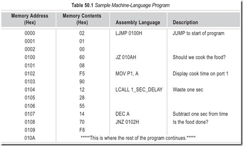
A very typical application of an embedded microprocessor is a microwave oven control system. A block diagram of such a system is shown in Fig. 50.8. If we were to try to analyse all of the machine- language instructions needed to program an actual microwave oven, you would find it overwhelming. Our goal here is to understand how a simple part of a program works and give you a glimpse of what the program does to control the system. In the example of Table 50.1 only a portion of a program is shown in a simplified form that you will find easy to understand. Its purpose is to determine if a non-zero value has been placed in the accumulator. The value in the accumulator represents the number of seconds that the microwave should cook the food. If a non-zero value is in A, it displays the number of seconds on an output port and counts down in 1 second interval until it reaches 0. It then continues with the rest of the program. The program starts executing at address 0000 when power is first applied, which resets the system. The instruction that is generally stored at the reset address is a jump instruction that sends the micro to the main program. The main program in this case starts at 0100, where it makes a decision either to jump immediately to the rest of the program at 010A or to execute the instructions from 0102–0109. In either case, it eventually executes the rest of the program from 010A until it is told to jump back to 0100 and do it all over again.
TYPES OF MICROWAVE OVENS
There are two main types of microwave ovens in the market. The first type cooks by microwaves only while the second is a microwave convection oven, which is in fact a combination of ovens. While microwave ovens remain popular, there is now a great demand for combination ovens also.
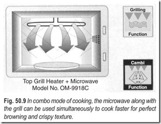
Most food cooks wonderfully well by the moist cooking method in microwave ovens, but certain food requires the dry heat produced in normal conventional ovens to turn it crisp and brown. This is when the second type of oven helps. Hence, some of the latest models have a combination of microwave and conventional ovens called the combo mode of cooking where the food automatically cooks by means of microwaves and then crisps by the conventional method, Fig. 50.9.
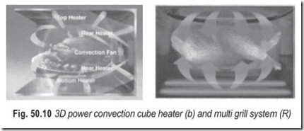
In multi-grill models, the 3D power system, Fig. 50.10 comprises of heaters placed at different places (top, bottom and rear) in the oven, together with a convection fan forming a cube heater. This not only cooks food evenly but also saves time. It allows you to do your own heat setting and helps to get the perfect crispy base, overcrispy top, or both at the same time.
MICROWAVE COOKING
Rapid microwave cooking provides excellent quality of food. This quick method of cooking using a minimum quantity of water helps retain most of the nutrients. In addition microwaving preserves natural flavours, while enhancing the colour and texture of the food.
Microwaves are non-ionising, high-frequency, short wavelength electromagnetic waves. Microwaves are attracted by the moisture in the food placed within the oven for cooking. The microwaves then penetrate the food surface, causing the moisture molecules to vibrate. This vibration generates heat which then cooks the food by conduction. The food is cooked from the outer surface to the inner core.
FEATURES DIAGRAM
Heating through microwaves has the following advantages over conventional electrical heating systems
1. Quicker heating saves time.
2. System is very clean.
3. Preserves natural flavours.
4. Retains most of the nutrients.
5. Enhances the colour and texture of food.
System can be combined with a conventional heating process.
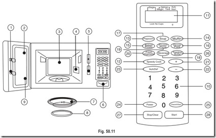
1. Door Latch – When the door is closed it will automatically lock shut. If the door is
opened while the oven is operating the magnetron will be automatically switched off.
2. Door Seal – The door seal maintains the microwave within the oven cavity and prevents microwave leakage.
3. Oven Cavity.
4. Spatter Shield – Protects the microwave outlet from splashes of cooking foods.
5. Safety Interlock System – Prevents the oven from operating while the door is opened.
6. Door Release Button – Pushing this button stops oven operation and opens the door.
7. Glass Cooking Tray – Made of special heat resistant glass. The tray must always be in
proper position before operating. Do not cook food directly on thetray.
8. Roller Guide – Supports the glass cooking tray.
9. Door Screen – Allows viewing of food. The screen is designed so that light can pass through, but not the microwaves.
10. Time Set Pad – Used to set the cooking time and the present time.
11. Display – Cooking time, power level, present time displayed.
12. Speedy Cook – Touch to set any desired reheat settle
13. Popcorn – Used to cook popcorn.
14. Muffin – Used to cook muffin.
15. Baked Potato – Used to bake potatoes.
16. Dinner Plate – Used to reheat dinner plate.
17. Soup – Used to reheat soup.
18. Beverage – Used to reheat beverage.
19. Frozen Pizza – Used to reheat frozen pizza.
20. Fresh Vegetable – Used to blanch fresh vegetable.
21. More – Used to add on one touch cooking.
22. Less – Used to remove one touch cooking.
23. Auto Defrost – Used to defrost foods.
24. Power – Used to set power level.
25. Clock/A. Start – Used to set clock & used to set auto settle.
26. Feeding Bottle – Used to sterilize bottle.
27. Stop/Clear – Used to stop the oven operation or to defrost.
28. Start – Used to start a selected operation.
WIRING INSTRUCTIONS
The wires in this mains cord are coloured in accordance with the following code.
Green : Earth Black : Neutral Red : Live
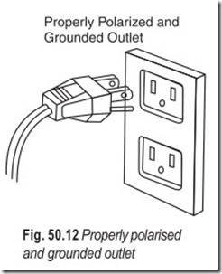
As the colours of the wires of the mainscord of this appliance may not correspond with the coloured marking identifying the terminals in your plug, proceed as follows : The wire which is coloured green must be connected to the terminal in the plug which is marked with the ‘E’ or by the earth symbol or green. The wire which is coloured black must be connected to the terminal which is marked with the letter ‘N’ or coloured black.
The wire which is coloured red must be connected to terminal which is marked with the letter ‘L’ or coloured red. Ensure proper wiring of the socket which should be of 15 Amps capacity. Line terminals should confirm to the above.
Warning : This appliance must be earthed properly.
SAFETY INSTRUCTIONS
Listed below are, as with other appliances, certain rules to follow and safeguards to assure best performance from this oven :
1. Do not use the oven for drying clothes, paper or any other nonfood item.
2. Do not use the oven without food items, this could damage the oven and may cause smoke emission.
3. Do not use the oven for storage of papers, cookbook, cookware, etc.
4. Do not operate the oven without glass tray. Be sure it is properly placed on the rotating base.
5. Ensure removal of caps or lids prior to cooking when you cook food sealed in bottles.
6. Do not put foreign material between the oven surface and door
which could result in excessive leakage of harmful microwave energy.
7. Do not use recycled paper products for cooking. They may contain impurities which could cause sparks and/or fires when used during cooking.
8. Use recommended & commercially packaged popcorn. Microwave popped corn produces a lower yield than conventional popping, there will be a number of unpopped kernels. Do not use oil unless specified by the manufacturer.
9. Do not pop popcorn longer than the manufacturer’s directions (popping time is generally below 3 minutes). Longer cooking does not yield more popped corn, it can cause scorchings and fire. Also, the cooking tray can become too hot to handle or may break.
10. Do not cook any food surrounded by a membranes such as egg yolks, potatoes, chicken livers, etc.,
without piercing them.
11. Should the microwave oven emit smoke indicating a fire, keep the oven door shut, switch the appliance off and disconnect the mains cord from the outlet.
12. When flammable food containers are used in the oven (e.g. packet popcorn) be sure to check the cooking process frequently to check for fire.
13. Always stir and/or shake the containers of baby foods prior to testing their temperature and serving the contents.
14. Always test the temperature of food or drink which has been heated in a microwave oven before serving, especially to children or elderly people. This is important because things which have been heated in a microwave oven keep on getting hotter even though the microwave oven cooking has stopped.
MICROWAVE COOKWARE
A wide variety of cookware can be used in the microwave oven, all of which are termed microproof to indicate that it is safe and recommended for microwave cooking. Most materials are microproof for at least a limited amount of cooking time. The principal exception to this rule is metal. Unless specifically approved, containers made of metal, even partially, are never to be used in the microwave oven. Not only does metal reflect microwaves, preventing them from entering a food, but it can also cause arcing, a condition where a static charge is conduced between the metal container and walls of your oven. Arcing is not dangerous to you, but it can deface your oven.
When selecting containers to cook in, be sure to consider what size will fit in your oven. After all, the cavity space of this oven is much smaller than the 2 to 2.5 cubic feet you are probably used to with your conventional oven. To familiarise yourself with the capacity of your microwave oven, it may be best to experiment with different container shapes and sizes.
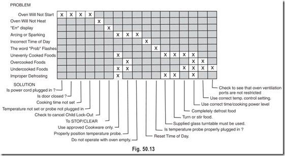
OPERATING PROBLEMS AND SOLUTIONS
You can often correct operating problems yourself. If your microwave oven fails to work properly, locate the operating problems in the chart below and try the solutions marked for each problem. If the microwave oven still does not work properly contact the nearest Service Centre, which are fully equipped to handle all of your service requirements.
CARE AND CLEANING
Wipe the oven inside and outside with a soft cloth and mild detergent solution. Then rinse and wipe dry. This should be done on a weekly basis—more often if needed. Never use rough powders or pads.
The inside oven top can be gently wiped in place. Excessive oil spatters on the inside top will be difficult to remove if left for many days.
Wipe spatters with a wet paper towel especially after cooking chicken or bacon.
IMPORTANT : If interior of the oven is not kept clean, the stirrer fan assembly will accumulate grease and food stains which will shorten the life of the stirrer fan assembly parts.
REMOVABLE PARTS
The following parts may be removed as described. They should be washed in warm (not hot) water with a mild detergent and a soft cloth. Once they are clean, rinse them well and dry with a soft cloth.
Never use rough cleaning powders, steel wool or rough cleaning pads.
(i) After each use of temperature probe, it must be removed from the socket. Use pot holder, as the wire, plug and sensor section may be hot. Wipe food or liquid from the sensor with a soft damp cloth.
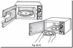
(ii) The glass turntable may be removed for cleaning at the sink. Wipe up spillovers with a paper towel or cloth before removal of the glass turntable. Be careful not to chip or scratch the edges of the glass turntable, as this may cause the glass turntable to break during use.
(iii) The turntable roller rest and oven cavity bottom should be cleaned regularly to avoid excessive noise. Simply wipe the oven bottom surface with mild detergent water and dry. The turntable roller rest may be washed in warm (not hot) water with a mild detergent and a soft cloth. Cooking vapours collect during repeated use, but in no way affects the oven bottom surface or roller rest wheels.
SPECIAL CARE
For best performance and safety, the inner door panel and the oven front frame should be free of food or grease build-up. Wipe both often with a mild detergent. Then rinse and wipe dry. Never use rough powders or pads.
After cleaning the control panel, touch STOP/CLEAR. This will clear any entries that might have been entered accidentally while cleaning the panel.
METAL RACK CARE
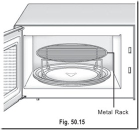
(i) The metal rack may get hot during cooking.
Pot holders may be needed to remove Rack after cooking.
(ii) Remove metal rack from oven when not being used for whole meal cooking.
(iii) Do not use browning dishes on metal rack.
(iv) Do not run the oven empty with the metal rack in it.
(v) Do not use foil or metal containers on the metal rack.
EXERCISES
Descriptive Questions
1. Explain the significance of microwaves.
2. Briefly explain transit time effect.
3. Explain the working of a multicavity magnetron.
4. What is the practical application of waveguides?
5. Explain the following :
(a) Wave reflector system (b) Dual-wave emission system
(c) Fail safe system in microwave ovens (d) 3D microwaves
6. Draw the block diagram of a microwave oven. Briefly explain each block.
7. What are the types of microwave ovens?
8. What are the advantages of microwave cooking?
9. With the help of a suitable block diagram explain the working of an LCD timer with alarm.
10. Briefly explain the working of a single-chip microcontroller.
Fill in the Blanks
1. The microwave oven uses microwaves of frequency …………………………
2. Electricity applied to the magnetron is used to create………………………….
3. The wave reflection system and dual-wave emission system ensure that food is………………………… cooked.
4. All microwave…………………………remains inside the oven.
5. Waveguides are the…………………………hardware.
6. Microwave energy is carried through the waveguide by…………………………along its inside walls.
7. The microwave oven is a…………………………device.
8. The anode of a magnetron is at a high…………………………potential.
9. The thermal protector in a microwave oven is a…………………………thermistor.
10. In LCD timer with alarm the keypad is the input and both the digital…………………………and………………………… are the output devices.
11. While the microwave oven remains popular there is now a greater demand for………………………….
12. Microwave cooking…………………………most of the nutrients and…………………………the colour and texture of food.
ANSWERS
Fill in the Blanks
|
1. 2.4 GHz |
2. microwave energy |
3. uniformly |
|
4. activity 7. fail safe 10. display; alarm buzzer |
5. inter connecting 8. negative 11. combination ovens |
6. reflection 9. PTC 12. retains; enhances |

