HAND WINDING, COIL FORMING, AND SLOT WEDGING
It is impractical to use preformed windings on small armatures. End room is limited and the windings must be drawn up tightly to the armature core. In large-production shops, small armatures are ma chine-wound on special equipment designed for the purpose. It is expedient to use preformed coils on large armatures, and this method should be used wherever practicable. Any rewinding job requires the utmost care to prevent the windings from short-circuiting to the metal core.
General Methods of Hand Winding
A hand winding is defined according to the method by which it is wound. There are five general methods of hand winding. They are: loop winding, chorded split-loop winding, split-V-loop winding, layer winding, and diametrically-split winding. The term “loop” is used to indicate that the wire is not cut at the start and finish of each coil. The term “chorded” means that the coil pitch is not full pitch. The advantages and disadvantages of these methods will be discussed under the appropriate headings, as will a general method of hand winding applicable to all of these windings.
Winding Procedure First Coil
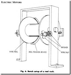
1 . Set up the reel of wire, of proper wire size for the armature, on a reel rack with a suitable reel-tension device, Fig. 6.
2 . Set the reel tension so that little mechanical resistance is offered to a pull on the wire. This resistance will cause the reel to stop and prevent the wire from becoming uncoiled when no longer pulled.
3 . For armatures requiring sleeving for lead identification, push lengths of cotton sleeving (dependent upon lead length) of alter nate colors on the wire. The number of cotton sleeve lengths will depend on the number of coils for the armature or the number of coils to be wound first. Use dissimilar colors for the beginning and ends of each coil. For example; red could be used for the beginning of a coil and white for the ending, and so on. Improvise a means for holding the sleeving back while drawing wire for the winding.
4. Mount a large armature in an armature stand.
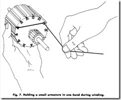
5 . Hold a small armature in one hand with the commutator end held toward the operator. Fig. 7.
6 . Insert the wire into a slot (choose any slot and call it slot 1) and hold the end of the wire down on the commutator with the thumb.
7 . Wind a few turns into the proper slots (coil pitch), pulling up each turn snug and firm but not to a point that the wire may snap or cut through the insulation.
8 . Release the end of the wire under the thumb and continue winding the coil, pulling each turn snug and firm, until the required number of turns is inserted for any one of the winding methods outlined in Loop Method of Winding with One Coil per Slot through Layer Winding as appears later in this chapter. Pay strict attention to coil pitch.
9 . Press down the windings with a stiff fiber drift plate to facilitate getting the required number of turns into a slot.
1 0 . Use a coil tamper, when necessary, to tamp and pack the winding in the slot when it appears that no more turns can be accom modated. Exercise care when using the tamper so that the winding insulation will not be damaged. After the use of the coil tamper, a surprising number of turns may be inserted.
1 1 . Secure the winding in the slot (see Securing Windings in the Slots). Exercise care when using the coil tamper so that the winding insulation will not be damaged.
1 2 . Move a length of sleeving to the end of the winding and loop the wire. This is the start of the next coil.
1 3 . Follow appropriate procedure according to method of winding for the rest of the coils.
Securing Windings in the Slots
Slot wedges are used for securing windings in the slots. These wedges are of three different types. The use of a particular type is dependent upon the available remaining space in the slot. They may be made of 1/32- or 1/16-inch thick fiber or wood, and where space is limited, they can be made of 0.015 to 0.023-inch fish paper. The selection and methods for application of wedges are given as follows:
1. Fish-paper wedges for well-filled slots. When the required
number of turns are in the slot and a wedge of an appreciable thickness cannot be driven in from the ends, a 0.023-inch fish paper wedge, cut just a trifle wider than the slot opening, is used and pressed into the slot from the top.
a. Put one edge of the wedge under one overhanging edge of the slot.
b. Drive the other side of the wedge down under the opposite edge of the slot with a narrow-width steel drift and hammer. (An old hacksaw blade with the teeth ground off can be used for a steel drift.) This method also applies to open-slot armatures. The wedge makes a driving fit, and after the armature has been dipped in varnish and baked, this type of wedging will hold as well as wedges driven in from the end.
2. . Driving in fish-paper, fiber, or wooden wedges. The selection of any one of these wedges depends on the available room in the slot and on the availability of the materials. Many times it may be necessary to drive two wedges of either the same thickness or odd thicknesses into a slot to hold the winding firmly in place. Cut enough wedges of proper length and width for the total number of slots. (If long lengths of prepared wedges are available, select the proper width and cut to proper length). Start a wedge in the slot end and, if possible, push it all the way in by hand. The wedge must fit tightly. If it just slips in, a wedge of greater thickness must be used. If the wedge cannot be pushed in by hand, follow the procedure given below.
a. Use a coil tamper in the slot and force down the windings in the slot end.
b. Start the wedge in the slot. Place the coil tamper slightly in front of the wedge, to open the slot. Keep advancing the tamper and working the wedge along behind it until the wedge completely fills the slot.
a. If a wooden or hard fiber wedge is used and it is difficult to drive it in by hand, tap the wedge in with rawhide or rubber mallet.
d. Use a wedge driver if the wedge bends when being driven into the slot. The wedge driver, however, is used as a last resort. If employed, the wedge is inserted into the outer shell of the wedge driver, leaving about 1/16 inch (1.6mm) of the wedge exposed. The exposed end of the wedge is started in the slot with the wedge driver’s outer shell aligned with the slot. Then the driving pin is tapped with a rawhide or rubber mallet until the entire length of the wedge is in the slot.
Loop Method of Winding With one Coil per Slot
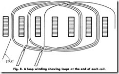
The most used winding method for small armatures is the loop method, Fig. 8. The advantage of this method is that it can be quickly applied and connected when correctly wound. The disadvantages are that the coils are not all alike, in that the first coil is smaller than the last. Also, where there is more than one coil per slot, the resistance of the last coil is greater than the first coil. As a result, the resistance of each coil is different. When the turns per coil are many or the wire size is large, the ends of the coils pile up so that it is difficult and sometimes impossible to wind in the coils properly. Due to the unequal size of the coils, a loop winding is not balanced and requires extreme care in balancing after winding. The procedure given below will aid in winding a loop winding.
1. Follow 1 to 11 in Winding Procedure-First Coil.
2. For armatures which will operate from 110-120 volts or higher, place strips of insulation between the overlapping end turns of the windings at the back and front of the armature.
3. Wind the second coil into the slot adjacent to the first slot according to the coil pitch, and identify the end of the coil winding with colored sleeving.
4. Make a loop of sufficient length to reach the commutator for connection, and identify the beginning of the third coil with colored sleeving.
5. Wind in the third coil and follow the same procedure for all the coils of the armature.
6. Cut the wire from the reel when the last turn of the last coil is inserted into the last slot, then connect the end to the single lead of the first coil.
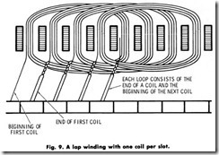
7. Lap windings (Fig. 9) can be wound left-hand or right-hand on either side of the shaft without affecting the direction of rotation of the motor or changing the brush polarity of a generator.
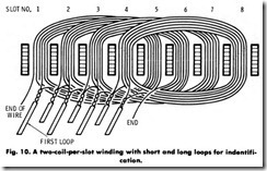
Loop Method of Winding with More Than one Coil per Slot The winding procedure for this type of loop winding is the same as in Winding Procedure-First Coil, except that there will be more than one coil in every slot. Fig. 10. For example, a 12-slot armature with 36 commutator bars will require 3 coils per slot. Every loop of these three coils must be marked with different colored sleeving. Red, white, and blue will be satisfactory, or any other combination of dissimilar colors. Sleeving can be used for one-fourth of the total number of coils of the armature and one-fourth the total number of coils loop-wound and identified. Then the wire is cut and identified. Winding and identifica tion is continued for the next one-fourth of the total number of windings. Continue this process unil the entire armature is wound. By this method each slot has three identified loops projecting, except at the end of each one-fourth of the total number of slots where there would be two identified loops and two identified ends.
Loop Method of Winding With More Than One Wire in Hand With this method, the coils are wound in place using two or more wires in hand. This is dependent upon the ratio of the number of commutator bars to the slots. For example, if there are 12 slots and 24 bars, 2 wires are fed into the slots from 2 wire reels. If there are 36 bars, 3 wires are fed into the slots from 3 wire reels. With this process, the wire is cut at the end of each coil and identified with sleeving which indicates the end of each coil. The wire is then brought around and the end turns to parallel the starting leads. Following the procedure of Winding Procedure-First Coil, for armatures operating from 110- 120 volts or higher, place strips of insulation between the overlapping end turns of the windings at the back and front of the armature.
Chorded, Split-Pitch Loop Winding
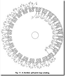
A feature of this winding (Fig. 11) is that two coils are wound in three slots on the same side of the shaft; two coil sides together in one slot and the other two coils each having a different pitch. The advantages of the chorded, split-pitch, winding is illustrated by a 5-horsepower, 1,100 r/min, two-pole motor having an armature 10 inches in diameter with 24 slots and 48 commutator bars. If this armature is wound full pitch, 1 and 13, the winding would pile up on the ends of the armature and take up too much space. By the use of the chorded, split-pitch, loop-winding method, the coil pitch is reduced to 80 percent of the full pitch, eliminating some of the coil crossings and preventing the end turns from bending around the shaft. For example, if the full pitch equals 12, 80 percent of the full pitch equals 9.6 or 0.80 x 12. This is equivalent to using slots 1 and 10.6. Since 0.6 of a slot is not possible, wind one coil in slots 1 and 11, with a pitch of 10, and one coil in slots 1 and 10, with a pitch of 9. The same procedure is carried out for all coil windings. This gives an average pitch of 9.5. This approximates the desired pitch of 9.6. With this particular type of winding, the long pitch 1 and 11, has one more turn than the short pitch, 1 and 10, and can only be wound with one wire in hand. The loops are made where the two coil sides are in the same slot and are identified according to the method shown in Identifying Coil Leads When Winding. For armatures operating from 110-120 volts or higher, place strips of insulation between the overlap ping end turns of the windings at the back and front of the armature. Check later in this chapter for connecting to the commutator.
Chorded, Split-Loop Winding
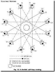
The last coils wound on the armature are visible on each side of the shaft and are parallel to each other, (Fig. 12). The advantages of a chorded, split-loop winding are better mechanical balance, more uni form coil resistance, and better coil distribution, resulting in more end room on the armature. The only disadvantage is that the wire is cut at the end of each coil and that connections to the commutator are slightly more complex in nature . The first coil is started as described in Winding Procedure-First Coil, Steps 1 to 7. Cut the wire and identify the ends, then turn the armature 180° and repeat the process for the second coil in the slot adjacent and to the right of the slot filled previously. Turn the armature 180° and skip the slot on the right adjacent to the previously filled slot and repeat the procedure for the third coil. Turn the armature 180° and repeat the procedure for the fourth coil in the slot and adjacent to the right of the slot filled previously. After winding in each coil, turn the armature 180°, repeat ing the aforementioned procedures until the entire armature is rewound. Place a strip of insulation between the group of end turns of one coil and the overlapping end turns of another coil at the back and front of the armature. Check later in this chapter for connections to the commutator.
Method of Putting on a Chorded, Split-Loop Winding When the Number of Slots is not Divisible by Four
The method of starting the top layer is slightly different from that already described. After six coils have been put in place, there will be one empty slot on each side of the armature. To start the seventh coil, skip two slots, counting clockwise from the starting side of coil 5, then start winding in slot 7 to the empty slot adjacent to the finish side of the coil 2 on the right. The coil parallel to coil 7, which is coil 8, will start in the slot with the finish side of coil2 and in the remaining empty slot, which is slot 6. The armature winding can now continue with the same procedure as was used on the bottom layer. A strip of insulation must be placed between the top layers and the bottom layers as described previously. The method of connecting this winding to the commutator will be described later in this chapter.
Split V-Loop Winding
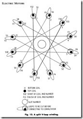
A distinctive feature of this winding (Fig. 13) is that the slots are filled as the winding progresses. The variation in coil lengths is about the same as in the chorded, split-loop winding. Its advantage over the chorded, split-loop winding is that it can be wound on a core with any number of slots. The first coil is started as described earlier in Winding Procedure-First Coil. For armatures operating from 110-120 volts or higher, place strips of insulation between the overlapping end turns of the windings at the back and front of the armature. After the first coil is wound into the slots of proper pitch on the right -hand side of the shaft and identified, the armature is rotated until the finished side of the coil is on top. Wind the second coil into the slot containing the finish side of coil 1, to the same pitch. Rotate the armature until the finish side of the second coil is on top. Wind the third coil into the slot containing the finish side of coil 2, to the same pitch. Follow this procedure for every coil until the armature is completely wound. See later part of the chapter for attaching to the commutator segments.
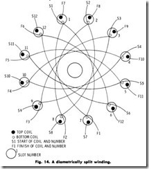
Diametrically Split Winding
This type of winding is most suitable for an armature with coils that require a few turns of heavy wire. (Fig. 14). It is recommended for machines that have an even number of slots for this type of winding. The hollow space between the shaft and windings is formed by using a wooden mandrel of the proper dimensions while winding the armature. Each coil is wound half on one side of the shaft and half on the other side of the shaft. To get an even distribution of the coil winding in the slots, wind two turns first on one side of the shaft, then two turns on the other side of the shaft and continue in this manner until the full number of turns for the coil are completed. Identify the start and finish of the coil and proceed to slot number 2. Follow the same procedure for every coil until the entire bottom layer is completed. There will be one identified lead at every slot for the bottom layer. The top layer is started in the slot which contains the finishing lead of the last coil in the bottom layer. Continue winding in the same manner, as outlined above until every slot contains a beginning and ending lead. Tie the last coil down by means of a heavy cord threaded underneath the other coils.
