Applications
Proximity detectors are basically metal detectors. They are used to detect the presence or absence of metal with- out physically touching it. This prevents wear on the unit and gives the detector the ability to sense red hot metals. Most proximity detectors are designed to detect ferrous metals only, but there are some units that detect all metals.
Circuit Operation
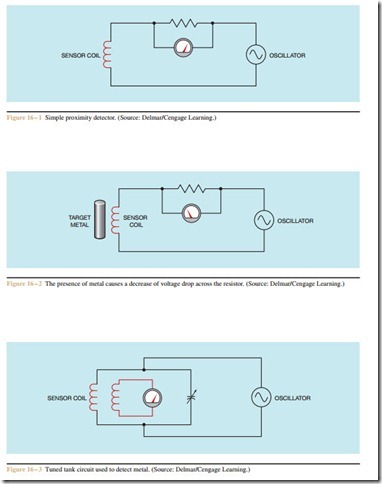
There are several methods used to make proximity detectors. One method is shown in Figure 16 – 1. This is a very simple circuit intended to illustrate the principle of operation of a proximity detector. The sensor coil is connected through a series resistor to an oscillator. A voltage detector, in this illustration a voltmeter, is connected across the resistor. Since AC voltage is applied to this circuit, the amount of current flow is determined by the resistance of the resistor and the inductive reactance of the coil. The voltage drop across the resistor is proportional to its resistance and the amount of current flow.
If ferrous metal is placed near the sensor coil, its inductance increases in value. This causes an increase in inductive reactance and a decrease in the amount of current flow through the circuit. When the current flow through the resistor is decreased, the voltage drop across the resistor decreases also (Figure 16 – 2). The drop in voltage can be used to turn relays or other devices on or off.
This method of detecting metal does not work well for all conditions. Another method, which is more sensitive to small amounts of metal, is shown in Figure 16 – 3. This detector uses a tank circuit tuned to the frequency of the oscillator. The sensor head con- tains two coils instead of one. This type of sensor is a small transformer. When the tank circuit is tuned to the frequency of the oscillator, current flow around the tank loop is high. This causes a high voltage to be induced into the secondary coil of the sensor head.
When ferrous metal is placed near the sensor, as shown in Figure 16 – 4, the inductance of the coil in- creases. When the inductance of the coil changes, the tank circuit no longer resonates to the frequency of the oscillator. This causes the current flow around the loop to decrease significantly. The decrease of current flow through the sensor coil causes the secondary voltage to drop, also.
Notice that both types of circuits depend on a ferrous metal to change the inductance of a coil. If a detector is to be used to detect nonferrous metals, some means other than changing the inductance of the coil must be used. An all-metal detector uses a tank circuit as shown in Figure 16 – 5. All-metal detectors operate at radio frequencies, and the balance of the tank circuit is used to keep the oscillator running. If the tank circuit becomes unbalanced, the oscillator stops operating. When a non- ferrous metal, such as aluminum, copper, or brass, is placed near the sensor coil, eddy currents are induced into the surface of the metal. The induction of eddy currents into the metal causes the tank circuit to become unbalanced and the oscillator to stop operating. When the oscillator stops operating, some other part of the circuit signals an output to turn on or off.
All-metal proximity detectors will sense ferrous met- als better than nonferrous. A ferrous metal can be sensed at about three times the distance of a nonferrous metal.
