Power supply service techniques
ALL ELECTRI CAL AND ELECTRONIC COMPONENTS IN YOUR prin ter, as well as every other piece of electronic equipment, require electrical power in order to function (figure 8-1). Power is always supplied in the form of voltage and current, and there must be adequate amounts of both to ensure the proper operation of each component. Unfortunately, the commercial ac power avail able from the wall outlets of your hom e, shop, or office , is not di rectly compatible with any components in a printer. As a result, ac power must be manipulated and converted into values of voltage and current that are suitable for your specific equipm ent. This is the task of a power supply.
The name power supply is rather a misleading one. A power sup ply (often designated PS) does not actually create power. Instead, it converts commercially generated and supplied ac power into one or more voltage levels that are better suited to particular tasks and components. ‘JYpical printer circuits require sources of 5, 12, 15, or 24 Vdc, usually several different voltages. In some printers (such as EP printers), the power supply can provide voltage levels much higher than the ac signal.
Power supplies are generally rugged and reliable devices, so much so that they are often overlooked or disregarded as possible prob lem sources. Yet, problems in the power supply can interfere with the printer’s normal operation, cause erratic or intermittent printer behavior, or shut down the afflicted printer outright. Luck ily, most supplies are reasonably simple to follow, and can be re paired or replaced with relative ease.There are many different PS circuits. Each design is optimized to suit the needs of the specific circuits that they must supply. In spite of the array of PS arrangements, there are only two typical operating modes: linear and switching. Both modes refer to the way in which a PS controls its output(s). This chapter shows you the construction, operations, characteristics, and repair consider ations for both power supply types.
Power supply hazards
All power supplies have one thing in common: they all handle raw ac power at some point. As detailed in Chapter 6, raw ac power can be extremely dangerous under the right circumstances. Tech nicians have been hurt (even killed) as a result of carelessness, so the threat of electrocution is very real while the printer is open and the power supply is exposed. The risk is greatest while taking power supply measurements on a running printer. Reducing the risk of electrocution is the main reason why you should keep the printer turned off and unplugged as much as possible during your repair. However, you can easily minimize these risks by taking some simple precautions as outlined in Chapter 6. If you have not yet read Chapter 6, take the time to review it now. If you feel that the risks inherent in power supply troubleshooting are just too great, do not attempt to troubleshoot the power supply. You can still correct power supply problems by replacing the entire power supply module outright while the printer is off and W1plugged.
Linear power supplies
The term linear means line or straight. As you might see from the block diagram of figure 8-2, a linear PS operates in essentially a straight line from ac input to de output. Components and power capacity vary radically between manufacturers and models, but all linear power supplies contain the same three basic subsections: a transformer, rectifier, and filter. The regulator block is also found in the majority of linear power supplies, but it is not mandatory for a minimum “working” supply. For the purposes of this book, all supplies will be regulated. The following sections outline the pur pose of each functional area.
Transformers
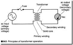
A transformer is used to alter the ac voltage and current charac teristics of ac input power. This allows ac to be converted into more useful levels of voltage and current. This important process of transformation is accomplished through the principles of mag netic coupling, as illustrated in the schematic of figure 8-3. Trans formers use two coils of solid wire wrapped along opposite sides of a common metal structure (called a core). Although figure 8-3 only illustrates two leads for each coil, many transformers offer a number of available leads (or taps) from both the primary and sec ondary coils. The core is built from laminated plates of “perme able” material (metal that can be magnetized). This serves not only as a physical base, but it is critical in concentrating magnetic fields around the transformer as well.
An ac voltage (or primary voltage), usually at 120 Vac, is applied across the primary winding of a transformer. The ac voltage causes current to fluctuate through the primary winding. In turn, this sets up a varying magnetic force field in the primary. The core concen trates this magnetic field and helps to transfer magnetic force to the secondary winding. Note that a solid core is not mandatory;
magnetic coupling between two coils can occur across an air gap, but solid cores make coupling much more efficient. This fluctuat ing magnetic field in the core cuts across the secondary winding, where it induces a secondary ac voltage between its terminals. Figure 8-3 shows an ac voltmeter measuring this voltage. This is the “transformer principle.”
Voltage across the secondary winding is directly proportional to the ratio of primary-to-secondary windings. For example, if there are 1,000 turns of wire in the primary coil and 100 turns of wire in the secondary coil, the ratio (called turns ratio) would be 10:1. Because there are fewer secondary windings than primary wind ings, that transformer is known as a step-down transformer. If 120 Vac were applied across the primary, its secondary would ide ally yield [120 Vac/(10/1)] 12 Vac. If the situation were reversed with 100 primary turns and 1,000 secondary turns, the trans former would be a 1:10 step-up transformer. An input of 12 Vac to this primary would result in an output of [12 Vac/(1/10)] 120 Vac across the secondary. An isolation transformer has a 1:1 turns ra tio; the number of primary and secondary turns is equal, so sec ondary voltage will ideally equal primary voltage.
A transformer also steps current, but it is stepped in reverse to the voltage ratio. If voltage is stepped up, current is stepped down by that same ratio, and vice versa. In this way, power taken from a transformer’s secondary will always (roughly) equal the power provided to its primary. As an example, suppose the transformer of figure 8-3 has 120 Vac at 0.1 A supplied to its primary. Primary power would then be [P=l x V] or [120 Vac x 0.1 A] 12 W. With a 10:1 step-down transformer, its secondary voltage would be 12 Vac, but [0.1 x (10/1)] 1A of current would be available. This re sults in a secondary power of [12 Vac x 1A] 12 W. On paper, power output always equals power input. In reality, however, output power is always slightly less than input power due to losses in the core and coil resistance. Severe losses can cause excessive heating in the transformer. The ratio of output power to input power [P/ 1 is known as efficiency. Most solid core transformers can reach 80% to 95% efficiency, but never 100%.
You might wonder why transformers will not step de voltages. Af ter all, de can produce a strong magnetic field in solenoids (impact print wires for example). While this is true, a magnetic field must fluctuate versus time in order to induce a potential (voltage) on another conductor. The de would certainly magnetize the primary winding, but without constant fluctuation, no voltage would be in duced across the secondary winding.
Rectifiers
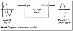
Secondary voltage across the transformer secondary is still in an ac form; that is, the polarity swings between positive and negative voltages. An ac voltage must be converted into de before it can be used by most electronic components. This conversion is known as rectification, where only one polarity of the input is allowed to reach the output, as shown in figure 8-4. Even though a rectifier’s output varies greatly, the polarity of its signal will always remain within one polarity (thus the term pulsating de). Diodes are ideal for use in rectifier circuits because they only allow current to flow in one direction. You will encounter three classical types of recti fier circuits: half wave, full wave, and diode bridge.
A half-wave rectifier circuit is shown in figure 8-5. It is the simplest and most straightforward type of rectifier circuit because it only requires one diode. As secondary ac voltage exceeds the turn-on
voltage of the diode (about 0.6 V for a silicon diode), it begins to conduct current. This generates an output that mimics the posi tive half of the ac input. If the diode were reversed, its output po larity would also be reversed. The disadvantage to this type of rectifier is that it is inefficient. A half-wave rectifier only deals with half of its ac input. The other half is basically ignored. The result ing gap between pulses results in a lower average output and a higher amount of ripple (ac noise) contained inthe fmal de signal. Half-wave rectifiers are rarely used in linear power supplies, but are used quite extensively in switching supply circuits.
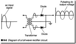
Full-wave rectifiers, such as the one shown in figure 8-6, offer some substantial performance advantages over the half-wave de sign. By using two diodes in the configuration shown, both polari ties of the ac secondary voltage input can be rectified into pulsating de. Because a diode is at each terminal of the secondary, polarities at each diode will be opposite as shown. When the ac sig nal is positive, the upper diode conducts, but the lower diode is cut off. When the ac signal becomes negative, the lower diode con ducts, but the upper diode is cut off. This means that one diode is always conducting, so there are no gaps in the fmal output signal. Ripple levels are lower and the average de output voltage is higher. The disadvantage to a full-wave rectifier is its transformer re quirement. A center-tapped secondary is needed to provide a ground reference for the supply. This often takes a slightly larger transformer, which is not a popular design choice among printer designers striving to reduce weight and bulle
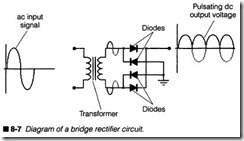
Diode bridge rectifiers use four rectifier diodes to provide full wave rectification without the troubles of a center-tapped trans-
Filters
former. Figure 8-7 illustrates a typical bridge rectifier stage. The ac voltage from the transformer secondary is connected to a series of diodes arranged in a “Wheatstone bridge” fashion. Diodes Dl and D2 provide the forward current paths, while D3 and D4 offer isolation between secondary voltage and a common reference point that serves as ground. When ac voltage is positive, diode D1 conducts because it is forward biased, and D4 provides isolation versus ground. As ac voltage becomes negative, D2 conducts while D3 supplies isolation versus ground. The complete bridge gener ates a full-wave pulsating de output. Bridges are by far the most popular type of rectifier circuit.
By strict technical definition, pulsating de is de because its polar ity remains consistent (even if its magnitude does change substantially). Unfortunately, even pulsating de is unsuitable for any type of electronics power source. Voltage levels must be constant over time in order to operate electronic devices properly. A filter is used to achieve a smoothed de voltage, as shown in figure 8-8. Ca pacitors are typically used as filter elements because they act as voltage storage devices, almost like light-duty batteries. When pul sating de is applied to a capacitive filter, as in figure 8-8, the ca pacitor charges with current supplied from the rectifier. Ultimately, the capacitor charges to the peak value of pulsating de. When a pulse falls off its peak (back toward zero), the capacitor will continue to supply current to a load. This action tends to hold up the output voltage over time (de is filtered).
However, filtering is not a perfect process. As current is drained away from the capacitor by its load, voltage across the filter will also drop. Voltage continues to drop until a new pulse of de recharges the filter for another cycle. This repetitive charge and discharge results in regular fluctuations of the filter output. These fluctuations are known as ripple, and ripple is an undesirable component of a smoothed de output.Figure 8-8 also shows a graph of voltage versus time for a typical filter circuit. The ideal de output would simply be a constant, flat
line at all points in time. In reality, there will always be some amount of filter ripple. Just how much ripple depends on the load. For a light load (a high resistance that draws relatively little cur rent), discharge is less between pulses, so ripple is also lower. A large load (a low resistance that draws fairly substantial current) requires greater current, so discharge (and ripple) is greater be tween pulses. The relationship of de pulses is shown for reference.
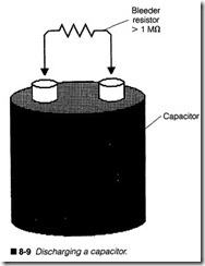
Additional filtering can be accomplished by adding more capaci tance to the filter stage. This holds more charge, so load can be supplied with less discharge. As a general rule, more capacitance results in less ripple, and vice versa. Although this is true in the ory, there are some practical limits to just how much capacitance can be used in a power filter. Size is always a big concern. Capaci tors larger than 4,700 F tend to be rather large and cumbersome. Above 10,000 J..LF, a filter can accept so much charging current on its initial charge (known as inrush current) that it might seem like a short circuit. Excessive inrush current can pop a fuse or even damage the rectifier stage.In addition to electrocution hazards from exposed ac lines, you must understand the potential for a filter shock hazard. Power ca pacitors tend to accumulate a substantial amount of electrical charge and hold it for a long time. If you touch the leads of a charged capacitor, current will flow through your body. This is usually not dangerous when the printer is unplugged; however, it can be very uncomfortable or it could result in a slight burn. To re move any stored charge in your filter stage, charge must be bled away in a controlled fashion, as shown in figure 8-9. A large-value resistor (called a bleeder resistor) can be connected across the filter. This will slowly drain away any remaining charge. Note that some filter capacitors might already be built with a bleeder resis tor. If a load remains connected across the filter, that too will dis charge the filter after power is removed. Never attempt to discharge a capacitor using a screwdriver or wire. The sudden re lease of energy can actually weld a wire or screwdriver blade right to the capacitor’s terminals, as well as damage the capacitor’s in ternal structure.
Regulators
A transformer, rectifier, and filter form the absolute essentials of every linear power supply. These parts combined will successfully convert ac into de that is capable of driving most electrical and elec tronic components. There are several troubles with these simple
“unregulated” supplies that make them undesirable. First, ripple is always present at a filter’s output. Under some circumstances, this can cause erratic operation in even the most forgiving ICs. Second, output voltage varies with load. While load is fairly light, this effect might be negligible, but the effects of heavy loads can also cause unpredictable circuit performance. For reliable circuit perfor mance, the filter’s output must be stabilized to eliminate effects of ripple and loading. This is the task of a regulator.
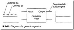
Linear regulation is just as its name implies; current flows from the regulator’s input to its outputs, as shown in figure 8-10. Voltage that is supplied to the regulator’s input must be somewhat higher than the desired output voltage (usually by several volts). Internal circuitry within the regulator manipulates input voltage to pro duce a steady, consistent output level over a fairly wide range of loads and input voltages. If input voltage drops below some mini mum value, the regulator falls out of regulation. In that case, the output signal tends to follow the input signal, including ripple.
In order to maintain a constant output voltage, the linear regulat ing circuit (or IC) will “throw away” extra energy provided by the filter in the form of heat. This is why most regulators are often at tached to large metal heat sinks. Heat is then carried away by the surrounding air. While linear regulation provides a simple and reli able method of operation, it is also very wasteful and inefficient. ‘l.YPicallinear regulators are only up to 50% efficient. This means that for every 10 W of power provided to the supply, only 5 W is provided to the load. Much of this waste occurs in the regu lation process. Switching regulation is much more efficient, but that is covered later in this chapter.
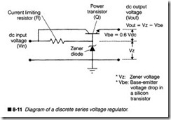
You might encounter many various types of regulator circuits. Figure 8-11 illustrates a very simple series voltage regulator constructed with discrete parts. Input voltage is applied to the zener diode (Zd) through a current-limiting resistor (Rz). The zener diode works to “clamp” voltage to its zener level. In turn, this zener potential turns on the power transistor, which allows load current to flow. Output voltage equals zener voltage minus a small
voltage drop (usually 0.5 to 0.7 V) from the transistor’s base-emit ter jun ction. You can set the output voltage by changing the zener diode.
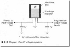
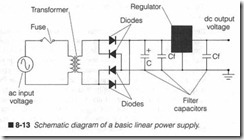
For the example of figure 8-11, suppose that input voltage is 10 V and you are using a 5.6-V zener diode. When power is applied to the circuit, zener voltage will be clamped at 5.6 V. Because input voltage is 10 V, the difference of 110 V-5.6 V] 4.4 V will appear across the current-limiting resistor Rz. Zener voltage saturates the transistor, so its output will be 5.6 V minus the transistor’s base emitter drop of 0.6 V, or 5.0 Vdc. As long as input voltage remains above the zener voltage , output voltage should remain steady re gardless of load; output is effectively regulated. Load current can be substantial, so you will often find a power transistor used as the regulatin g transistor.Regulator circuits can easily be fabricated as integrated circuits, as shown in figure 8-12. Additional performance features such as automatic cmrent limiting and over-temperatme shut-down cir cuitry can be included to improve the regulator’s reliability. Input voltage must still exceed some minimum level to achieve a steady output, but IC regulators are much simpler to use. One additional consideration for IC regulators is the addition of high -frequency filter capacitors at both the input and output. These serve to filter out any high -frequency noise or signals that could interfere with the regulator’s operation. HF filters are generally small-value, non polariz ed capacitors (0.01jlF or O.ljJ.F). A complete linear power supply is shown in figure 8-13.
Linear supplies in printers
Generally speaking, linear power supplies are simple, inexpensive , and reliable devices. In actual practice , however, few printers use linear power supply technology. You see, mod ern computer print ers demand substantial amounts of power (especially EP print ers), but the inherent inefficiency of linear power supplies would result in serious heat dissipation, which is undesirable. As a con sequence, most commercial printers will employ switching power supplies as discussed later in this chapter. Linear supplies will usu ally be employed in low-power applications such as ac adapter modules for mobile printers. You might wonder why we have cov ered linear supplies in such detail when they are used so infre quently. The reason is that the principles behind switching power supplies are virtually identical to those of linear supplies; only the regulation technique is different. So by learning about linear sup plies, you cover much of switching supplies as well. You will also see that portions of the switching supply are essentially linear sup ply circuits.
Troubleshooting a linear supply
An important factor to keep in mind when troubleshooting a linear supply is that they tend to run hot, sometimes very hot, so be sure to allow 10 or 15 minutes for the regulator heat sink(s) to cool be fore attempting to replace the component. If you will be taking measurements on the “live” circuit, be careful to avoid touching heat sink fins. Another caution is the filter capacitors, which tend to be rather large. Allowing a few minutes of idle time (with the printer off and unplugged) before checking a capacitor allows the filter to discharge and reduce the possibility of a jolt. Once again,
if you must run powered tests on the supply, take all precautions to avoid electrocution.
Under most circumstances, linear power supplies are reasonably straightforward to troubleshoot. The relatively small number of components, along with a simple “input-to-output” circuit layout, makes following the circuit far less challenging than logic circuits. A sound procedure for linear supplies is often to use your volt meter (or oscilloscope) to trace the presence of voltage from the output back through the supply. If an output has failed, start your measurements at that output and work backwards into the circuit until you fmd the appropriate signal again. The following symp toms and troubleshooting procedures present more details. Of course, you can also replace the power supply module outright.
Symptoms
Symptom 1 Power supply is completely dead. Printer does not op erate and no power indicators are lit. Before you begin to disas semble the printer, check to make sure that you are receiving an appropriate amount of ac line voltage into the power supply. Use your multimeter to measure ac voltage at the wall outlet powering your printer. Normally, you should read between 105 and 130 Vac (210 to 240 Vac in Europe) for a power supply to operate properly.
More or less ac line voltage can cause the power supply to mal function. Inspect the printer where the ac line cord connects; you might notice a red line voltage switch that allows the power supply to be set for 120-V or 220-V operation. If your printer has a line volt age switch, see that it is set for the appropriate level. For example, if there is 120 Vac available, but the line voltage switch is set for 220 Vac, the power supply (and the whole printer) will not work. Exer cise extreme caution whenever measuring ac line voltage levels. Review the hazards of electricity as discussed in Chapter 6.
When you determine that an appropriate amount of ac is available at the printer, the fault probably exists in the printer itself. Check the printer’s power switch to be sure that it is turned on. Even though it sounds silly, this really is a common oversight. Next, check the printer’s main line fuse, which is often located close to the ac line cord. Remember to unplug the printer before removing the fuse for examination. You should find the fusible link intact, but it is not always possible to see the entire link. Use your multi meter to measure continuity across the fuse. Normally, a working fuse should read as a short circuit (0 0). If you read infinite resis tance, the fuse is defective and should be replaced. Use caution
when replacing fuses. Use only fuses of the same amperage and voltage ratings. If a new fuse fails immediately when replaced, it suggests a serious failure (such as a short circuit) elsewhere in the power supply or the printer’s internal circuitry. Do not continue to replace fuses if they continuously fail.
If everything checks properly up to this point, suspect a fault in the power supply module. You must disassemble your printer and work on the power supply. Take all precautions to protect yourself from electrocution hazards. First, check all connectors and wiring leading to or from the supply to rule out a broken wire or loose connector. Tum on printer power and use your multimeter to measure de output voltage(s) from the supply. A typical printer power supply will deliver two voltages (usually +5 Vdc and +24 Vdc), and most printed circuit markings will give you some indica tion of what voltage should exist at each respective output. A low or nonexistent output indicates a problem. To make sure that the output(s) are not being shorted by their loads, disconnect the sup ply from its load and measure the output(s) again. If your readings climb up to a normal level, chances are that the power supply itself is functional, but there might be a short circuit elsewhere in the printer’s electronics. If voltage readings remain low, you will have to troubleshoot the supply. For the purposes of this discussion, refer to the diagram of figure 8-13. If you do not have the time, equipment, or inclination to troubleshoot the printer’s power sup ply, you should replace it outright.
A linear troubleshooting process
If the voltage output is completely zero, check for the presence of a de (low voltage) protection fuse. Some power supplies, espe cially high-end supplies, fuse each output in addition to the ac in put. You might fmd normally sized fuses in the power supply itself, but other fuses might also be located around the printer’s ECU. Look carefully for any subminiature or “pico” fuses (resembling carbon fllm resistors). You will need to tum off and unplug the printer, then test each one.
Of all the components in your supply, the regulator carries the greatest stress. Use your multimeter to measure the de input to the regulator. You should read several volts greater than the ex pected output. For example, a regulator with an output of +5 Vde requires an input of +7 or +8 Vde. When the regulator’s input volt age is correct, but its output is not, the regulator is probably de fective and should be replaced. A low or nonexistent regulator input suggests a faulty filter or rectifier.
A shorted power filter capacitor can pull down the output from a rectifier. Turn off and unplug the printer, remove at least one ca pacitor lead from its circuit, and test the capacitor as discussed in the test equipment section of Chapter 5. Replace any filter capac itor that appears open or shorted. Any power capacitor that ap pears hot or emits a strong pungent odor should be a clear indication of trouble. Be sure to replace filter capacitors with iden tical devices, and take care to observe any polarity markings.
Inspect the rectifier circuit carefully. A faulty rectifier diode can completely disable your supply. Turn off and unplug the printer, then test each rectifier diode as discussed in the test equipment section of Chapter 5. When a bridge rectifier fails, you will usually find the two forward diodes open circuited. Replace any diodes that appear open or short circuited. If your rectifier is built into a potted bridge module, the entire module must be replaced.
Finally, turn on printer power and check the ac voltages at the transformer’s primary and secondary windings. Use extreme cau tion when measuring ac voltage levels. You should find about 120 Vac across the primary (about 220 Vac in Europe) and some lower amount of ac (usually about 30 Vac) across the secondary. Where there are multiple taps from the secondary winding, you should measure the output on each tap. An open circuit in either the pri mary or secondary winding can prevent any secondary output. Check for shorted transformer windings, and be suspicious of a transformer that becomes very hot after a short period of use, or one that emits an audible 50-60 Hz hum. Such a transformer might be developing a short circuit.
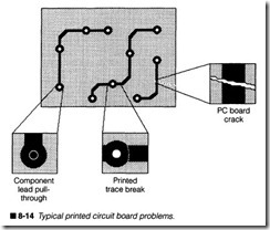
Consider the possibility of a printed circuit board failure, espe cially if the printer failed after being dropped or abused. Faulty soldering at the factory or on the repair bench can also cause a PC board problem. You might see printed circuits referred to as printed wiring boards (or PWBs). As figure 8-14 illustrates, there are three different kinds of problems that can plague a printed circuit: lead pull-through, trace break, and board crack.
Lead pull-through occurs when a component lead or wire is ripped away from its through-hole. Often, the soldering at the printed cir cuit pad might appear perfectly normal, but there will be a hole in the middle where the lead was. The lead might remain within its printed circuit hole, but it might not be fully connected. This kind of problem can easily result in bizarre, intermittent behavior, but it can be repaired simply by reheating the solder joint and applying fresh solder to reestablish the connection.
Trace break occurs commonly around large or awkward compo nents that are too well soldered or mechanically attached to experience lead pull-through. Instead, physical force will break the solder pad away from its trace. Trace breaks are difficult to detect because they are usually so fine and clean that you might not see them during a visual inspection. You have to spot them by wiggling each lead individually. When a solder pad moves, but its trace does not, you will see the break location. Jumper between two adjacent solder pads to reliably repair this failure. Do not attempt to solder or jumper across the break itself. Chemical coatings applied to printed circuit boards prevent solder from sticking to trace areas.
Board cracks accompany such physical traumas as drops or other abuse. Impact forces can actually crack the circuit board. This, in turn, can split any traces that might be over it. Luckily, board cracks are relatively easy to spot because they leave a long, discol ored line along the PC board. As with trace breaks, you must jumper between two adjacent solder pads to make a reliable repair rather than soldering across the break itself. If you detect an ex tensive board crack, however, you should replace the board rather than attempt to repair it.
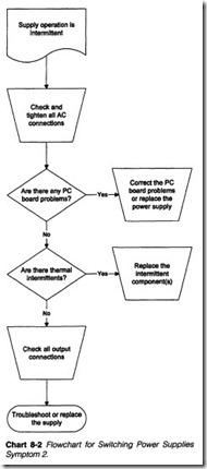
Symptom 2 Supply operation is intermittent. Printer operation cuts in and out along with the supply. Begin by inspecting the ac line voltage powering your printer. If your line cord is loose at the wall plug or printer, it can play havoc with printer operation. Use extreme caution when dealing with ac line voltages to prevent in juries from electrical shock. Also check the integrity of any ac con nections within the printer, along with any output connectors attached to the printer’s internal circuitry. Tighten or replace any connectors that appear to be loose.
Check the power supply printed circuit board for any signs of fail ure, especially if the printer started malfunctioning after a drop or other physical abuse. Faulty soldering connections from the fac tory (or from your workbench) can also cause printed circuit fail ures. Review figure 8-14 for three typical printed circuit problems. If you do not have the time, equipment, or inclination to trou bleshoot the power supply, you should replace it outright.
Lead pull-through is a fault that occurs anywhere a component lead or wire is soldered into a through-hole. Sudden, sharp force applied to the lead can overcome the connection’s strength and rip the lead right away from its solder joint. This might or might not pull the lead from its hole entirely. Trace breaks can happen any where a round solder pad meets a printed trace. Sudden impacts that do’ not cause lead pull-through might cause a hairline fracture between the solder pad and its printed trace. These can be partic ularly difficult problems because it might not ‘be possible to see trace breaks on visual inspection. You might have to wiggle each solder pad gently to reveal any trace breaks. Board cracks are fairly obvious problems, but large cracks can sever a great number of traces; your decision on whether or not to repair or replace the board really depends on the crack size and board complexity. As a general rule, breaks or cracks can be corrected by soldering jumpers between the solder pads across each defect.
Consider the possibility of thermal intermittents if your printer works fme when it is first turned on, but fails after some period of operation. Often, the printer must sit for a time with all power off before its operation will return. Test for thermally intermittent components by spraying suspect parts with a liquid refrigerant (available from just about any electronics parts store or mail-order house).
Begin by exposing the power supply. Apply power and operate the printer until it fails. Use your multimeter to measure each supply output before and after it fails. This will tell you what outputs are failing. When you have identified a faulty output, check its regula tor for excessive heat. Never touch live components that might be hot or carrying high voltages; it is a certain opportunity for injury! Instead, smell around the regulator for any trace of smoke or un usually heated air. Spray the regulator with refrigerant, wait a mo ment, and recheck your output voltage. If normal voltage returns temporarily, you have isolated the problem. Replace the faulty reg ulator. Keep in mind that you might have to spray a component several times to cool it properly. OP.e common mistake many novice troubleshooters make is their random use of refrigerant. If you spray several components at a time, you will not be able to de termine where the fault is, so concentrate on only one component (such as the regulator) at a time.
Filter components and rectifier diodes are rarely subject to ther mal problems. Transformer windings can open or short due to ex cessive heat, but only after a long period of breakdown. Use your multimeter to measure voltages through the remainder of the sup ply in order to track down any further problems.
Symptom 3 Printer is not operating properly. It might be function ing erratically or not at all. Power indicators might or might not be lit. Use your multimeter to measure the ac line voltage reaching the printer. Under normal circumstances, you should measure 105 to 130 Vac (some European countries use 210 to 240 Vac). On the average, 120 Vac should be available. If line voltage drops below 105 Vac, power supply outputs can begin to fall out of regulation. As a result, printer circuits might not receive enough voltage or current to ensure proper operation. This can cause erratic opera tion that can disable (or even damage) the printer. High input volt ages (over 130 Vac) can force more current into the supply than desirable. Additional current generates heat, which can cause pre mature breakdowns in the power supply.
Tum off and unplug the printer, then check for any loose connec tors or wiring that might be interrupting circuit operation. They might have been improperly installed at the factory, or you might have reinstalled them incorrectly during a previous repair. Restore printer power and use your multimeter to measure voltage at each supply output. If you locate a defective output, troubleshoot the supply from its output, back to its transformer as discussed in Symptom 1, or replace the power supply module entirely. If all supply outputs appear correct, there might be a fault in the printer’s ECU, so troubleshoot your printer electronics according to the procedures outlined in Chapter 9, or replace the ECU out right.
If you detect a faulty supply output, use your multimeter to mea sure input voltage at that regulator. It should be several volts higher than the expected regulator output. When a regulator’s in put appears normal, but its output does not, try replacing the reg ulator. A low or nonexistent regulator input voltage might be caused by a fault in the filter or rectifier stages. Unplug the printer and check your filter capacitor(s) and rectifier diodes for open or short circuits, as discussed in the test equipment section of Chap ter 5. Replace any filter capacitors or rectifier diodes that appear defective, or replace the power supply.
Switching power supplies
The great disadvantage to linear power supplies is their tremen dous waste. At least half of all power provided to a linear supply is literally thrown away as heat; most of this waste occurs in the reg ulator. Ideally, if there was just enough energy supplied to the reg ulator to achieve a stable output voltage, regulator waste could be reduced almost entirely, and supply efficiency would be improved dramatically.
Understanding switching regulation
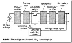
Instead of throwing away extra input energy, a switching power supply senses the output voltage provided to a load, then switches the ac primary (or secondary) voltage on or off as needed to main tain steady levels. A block diagram of a typical switching power supply is shown in figure 8-15. There are a variety of circuit con figurations that are possible, but figure 8-15 illustrates one possible design. You can see the similarities and differences between a switching supply and the linear supply shown in figure 8-2.
An ac line voltage entering the supply is immediately converted to pulsating de, then filtered to provide a “primary de” voltage. No tice that ac is not transformed before rectification, so primary de can reach levels approaching 170 V. Remember that ac is 120 Vnns.
Because capacitors charge to the peak voltage (peak = rms x 1.414), de levels can be higher than your ac voltmeter readings.
This is as dangerous as ac line voltage, and should be treated with extreme caution.
On start-up, the switching transistor is turned on and off at a high frequency (usually 20 to 40 kHz), and a long duty cycle. The switching transistor breaks up this primary de into chopped de, which can now be used as the primary signal for a step-down
transformer. The duty cycle of chopped de will affect the ac volt age level generated on the transformer’s secondary. A long duty cycle means a larger output voltage (for heavy loads), and a short duty cycle means lower output voltage (for light loads). Duty cy cle itself refers to the amount of time that a signal is “on” com pared to its overall cycle. Duty cycle is continuously adjusted by the sensing/switching circuit. You can use an oscilloscope to view switching and chopped de signals.
The ac voltage produced on the transformer’s secondary winding (typically a step-down transformer) is not a pure sine wave, but it alternates regularly enough to be treated as ac by the remainder of the supply. Secondary voltage is rerectified and refiltered to form a “secondary de” voltage that is actually applied to the load. Out put voltage is sensed by the sensing/switching circuit, which con stantly adjusts the chopped de duty cycle.
As load increases on the secondary circuit (more current is drawn by the load), output voltage tends to drop. This is perfectly nor mal; the same thing happens in every unregulated supply. How ever, a sensing circuit detects this voltage drop and increases the switching duty cycle. In turn, the duty cycle for chopped de in creases, which increases the voltage produced by the secondary winding. Output voltage climbs back up again to its desired value; output voltage is regulated.
The reverse will happen as load decreases on the secondary cir cuit (less current is drawn by the load). A smaller load will tend to make output voltage climb. Again, the same actions happen in an unregulated supply. The sensing/switching circuit detects this increase in voltage and reduces the switching duty cycle. As a result, the duty cycle for chopped de decreases, and transformer sec ondary voltage decreases. Output voltage drops back to its desired value; output voltage remains regulated.
Switching supply trade-offs
Consider the advantages of a switching power supply. Current is only drawn in the primary circuit when its switching transistor is on, so very little power is wasted in the primary circuit. The sec ondary circuit will supply just enough power to keep load voltage constant (regulated), but very little power is wasted by the sec ondary rectifier, filter, or switching circuit. Switching power sup plies can reach efficiencies higher than 85% (35% more efficient than most comparable linear supplies). More efficiency means less heat is generated by the supply, so components can be smaller and packaged more tightly.Unfortunately, there are several disadvantages to switching sup plies that you must be aware of. First, switching supplies tend to act as radio transmitters. Their switching frequencies can wreak havoc in radio and television reception, not to mention its own cir cuits inside the printer. This is because most switching supplies are somehow covered or shielded in a metal casing. It is critically important that you replace any shielding removed during your re pair. Strong electromagnetic interference (EMI) can disturb the printer’s electronics. Second, the output voltage will always con tain some amount of high-frequency ripple. In many applications, this is not enough noise to present interference to the load. In fact, virtually all printers use switching power supplies. Finally, a switching supply often contains more components, and its “feed back loop” configuration is more difficult to troubleshoot than a linear supply. This is often outweighed by the smaller, lighter packaging of a switching supply.
A dot-matrix switching supply
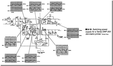
Now that you understand the important concepts and operations behind switching power supplies, you can take a detailed look at two practical switching supplies. The power supply for a Tandy DMP 203 is illustrated in figure 8-16. You can see the demarcation line between the primary and secondary sides of the supply at the transformer Tl. Raw ac power enters the supply when switch SWl is closed. The inductor Ll serves as a filter, and diode bridge DBl is the primary rectifier. If you look at the positive side of C2 with
an oscilloscope, you will find about 170 Vdc. Remember that this amount of de is every bit as hazardous as ac, so take all precau tions to protect yourself from injury. If you look at the junction of J3 and D2 in the schematic, you will find an even higher level of de (about 275 V).
Now, the high de signal must be “chopped” before it can be trans formed by T1. Transistors Q1and Q2 (with their associated bias ing components) form an oscillator that breaks up de into repetitive signals (such as the 12-VP-P signal at transformer pri mary winding V2). There are some interesting points to note about this process. First, the chopped signals are not sinusoidal. While that would yield the best results, the repeating signals are close enough to support transformation across Tl. Second, there are two primary and two secondary windings on T1; in effect, T1 acts as two separate transformers.Now remember that the switching circuit requires a sensing signal that is fed back from the output. The feedback signal is supplied from the optoisolator PC1, which is driven from the 24-V output. The advantage of an optoisolator is that the primary and sec ondary circuits are entirely isolated, so a fault in one side will have less damaging effects on the other side. It is also important to note that the optoisolator and its adjacent components are vital to the proper operation of the supply. A fault in PC1, ZD4, Q4, and so on, will disable the entire supply.
Once the chopped signals are transformed by T1, the secondary signals are fed to two separate secondary power circuits, a 5-V cir cuit and a 24-V circuit. As you might notice, each of the secondary circuits is basically a simple linear power supply. For the +5-V output, diode D5 forms a half-wave rectifier, while C9 provides fil tering (you’ll see about +7 V across C9 with your oscilloscope). Transistor Q3 and zener diode ZD 1 act as a series voltage regula tor, which clamps the output to 5 V. Capacitor C11 merely pro vides additional filtering to the output signal.
The 24-V power supply is quite similar. Because the 24 Vis in tended to operate high-power devices, such as motors and print solenoids, the output does not need high-performance regulation. Diode D7 acts as a half-wave rectifier, and the pulsating de is fil tered by C13. Zener diode ZD2 provides a low level of regulation, basically minimizing electrical variations by clamping the output to 24 V. Resistor R16 works as a load resistor for the power supply, which doubles as a bleeder resistor for the beefy 4,700-J..lF filter capacitor.
An EP switching supply
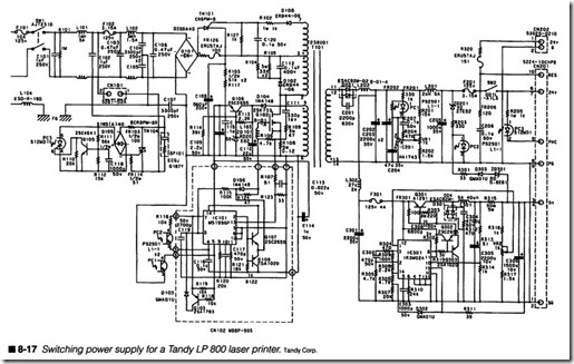
The power supply circuit shown in figure 8-17 illustrates the same basic principles as figure 8-16, but this new design incorporates a series of sophisticated enhancements. Because this supply is in tended for an EP printer, it must be capable of providing more power and stability than the circuit of figure 8-16. As a conse quence, much of the added complexity is included to accommo date those two objectives. But ultimately, the supply in figure 8-17 will provide three outputs: a +5-Vde output for the ECU logic, a +24-Vde output to support the printer’s motors and electro mechanical clutches, and a separate +24-Vde output designed to drive the fusing heater.All of the detailed circuit descriptions are not covered here; that would take a small chapter itself. However there are some impor tant similarities and differences that you should recognize. The ac enters the supply and is initially fused by F101. The arrangement of inductors and capacitors around the supplemental fuse F102 serve as surge and electrical noise suppressors. The small circuit arrangement below CN101 is the switching regulator circuitry that controls the fusing heater voltage. For the +5- and +24-V circuits, initial rectification is provided by the bridge rectifier D101. The bulk of active components around Q106, Q102, and IC101 form the sensing and switching network that breaks the high de level into the chopped ac, which feeds transformer T1.
The single secondary output of T1 feeds acto the +24- and +5-V regulator circuits. Note that both output circuits are fed from one half-wave rectifier (D201). As with figure 8-16, the secondary cir cuitry in the +24-V arm is responsible for developing and filtering the actual output voltage. Note the added complexity that is needed to support a more demanding motor system, as well as a laser and scanning system. To achieve optimum performance, the +24-V output is adjustable through VRl. Note also the added com plexity of the +5-V circuit. This is necessary to support the exten sive logic used in an EP printer. Voltage must be maintained within very tight margins in spite of the large current load; this is the re sponsibility of IC301 and associated circuitry. The +24-V output is fused by F201, while the +5-V output is fused by F301. With a to tal of four fuses in the power supply, you can see why it is so im portant to check the fuses before wasting time by troubleshooting a supply, which might not be defective. Another point to observe is that isolation between the primary and secondary circuits is pro vided by three individual optoisolators (PC1, PC2, and PC3) instead of the single optoisolator in figure 8-16. This affords inde pendent control over each output.
Troubleshooting a switching supply
When you consider the intricacies of a switching power supply, you can start to understand the difficulties associated in trou bleshooting such a circuit. Tracing high-energy analog signals that feed back on themselves in this manner can be a time-consuming challenge even for experienced technicians. As a result, you should evaluate the economics of replacing the supply outright, rather than spending the time to troubleshoot it. Of course, en thusiasts with the time and inclination to perform such trou bleshooting might find the challenge very rewarding. Still, subassembly replacement remains a viable option. The following section outlines a series of procedures for dealing with switching supply problems. For the purposes of this discussion, refer to the supply shown in figure 8-16.
Symptoms
Symptom 1 Power supply is completely dead. Printer does not operate, and no power indicators are lit. Refer to Chart 8-1. Before you begin to disassemble the printer, check to make sure that you are receiving an appropriate amount of ac line voltage into the power supply. Use your multimeter to measure ac voltage at the wall outlet powering your printer. Normally, you should read be tween 105 and 130 Vac (210 to 240 Vac in Europe) for a power supply to operate properly. More or less ac line voltage can cause the power supply to malfunction. Inspect the printer where the ac line cord connects; you might notice a red line voltage switch that allows the power supply to be set for 120 V or 220 V operation. If your printer has a line voltage switch, see that it is set for the ap propriate level. For example, if there is 120 Vac available, but the line voltage switch is set for 220 Vac, the power supply (and the whole printer) will not work. Exercise extreme caution whenever measuring ac line voltage levels. Review the hazards of electricity, as discussed in Chapter 6.
When you determine that an appropriate amount of ac is available at the printer, the fault probably exists in the printer itself. Check the printer’s power switch to be sure that it is turned on. Even though it sounds silly, this really is a common oversight. Next, check the printer’s main line fuse (i.e., fuse F1 in figure 8-16), which is often located close to the ac line cord. Remember to un-
plug the printer before removing the fuse for examination. You should find the fusible link intact, but it is not always possible to see the entire link. Use your multimeter to measure continuity across the fuse. Normally, a working fuse should read as a short circuit (0 Q). If you read infinite resistance, the fuse is defective and should be replaced. Use caution when replacing fuses. Use only fuses of the same amperage and voltage ratings. If a new fuse fails immediately when replaced, it suggests a serious failure (such as a short circuit) elsewhere in the power supply or the printer’s internal circuitry. Do not continue to replace fuses if they contin uously fail.
If everything checks properly up to this point, suspect a fault in the power supply module. You must disassemble your printer and work on the power supply. Take all precautions to protect yourself from electrocution hazards. First, check all connectors and wiring leading to or from the supply to rule out a broken wire or loose connector. This is especially important for switching supplies be cause proper switching depends on having the proper load at tached. If the load circuit (i.e., the ECU) is disconnected, you might not get proper outputs (if any) from the supply, or the out puts might fluctuate wildly. Turn on printer power and use your multimeter to measure de output voltage(s) from the supply. The supply in figure 8-16 will deliver two voltages (+5 Vdc and +24 Vde), and most printed circuit markings will give you some indica tion of what voltage should exist at each respective output. A low or nonexistent output indicates a problem. If you do not have the time, equipment, or inclination to troubleshoot the printer’s power supply, you should replace it outright.
A switching troubleshooting process
When switching supply outputs continue to measure incorrectly with all connectors and wiring intact, your problem is probably in side the supply. With a linear supply, you generally begin testing at the output, then work back toward the ac input. But for a switch ing supply, you should begin testing at the ac input, then work to ward the defective output. Refer to figure 8-16.
Measure ac entering the supply (i.e., across the inductor L1 enter ing the bridge rectifier DB1). If ac is absent, the current filter 11 might be defective and should be checked and replaced if neces sary. Be sure to take all precautions to protect yourself from injury when measuring ac voltages. Next, check the de level across the output of diode bridge DB1. Because the bridge is rectifying raw (untransformed) ac, you will read at least 170 Vde. If this level is low or absent, the diode bridge might be defective, and should be checked and replaced.
Now, check the chopped ac levels across the transformer’s primary windings. You can see typical oscilloscope patterns shown in figure 8-16. If chopped ac is missing, there is a defect in the sensing/ switching circuit that you will need to isolate by turning off all power, then checking the active switching components (i.e., Q1, Q2, Q4, PCl, and their associated diodes). A fault in any one of these components will interrupt the oscillator circuit and disable the entire supply. Also keep in mind that high-frequency oscillator operation can fatigue capacitors in the switching circuit as well, and I have seen capacitors exhibit thermal intermittent operation (where the supply works when first turned on, but gradual heat buildup during operation causes the marginal capacitor(s) to fail and shut down the supply). As a rule, the probability of compo nent failure is: transistors, diodes, capacitors, resistors, and trans formers (with transistors the most likely devices to fail).If you fmd the chopped ac signal available on the primary wind ings, check for secondary signals. If the secondary ac signal is missing, the transformer has failed, or there is a problem with the PC board contacts. For the circuit of figure 8-16, it is unlikely that both secondary windings (and thus both outputs) will fail simulta neously, so when only one output is lost, you can usually begin testing at the transformer.
However, common secondary designs, like figure 8-17, will disable all outputs when the secondary fails.
From here on, you are fundamentally testing individual linear sup ply circuits. For the +5-V circuit, rectification is supplied by diode D5, filtering is handled by capacitor C9, and regulation is provided by the combination of Q3 and ZD1 (biased by R7, R8, and ClO). The capacitor C11 merely supplies some supplemental filtering. If secondary ac is present, and the output is low or absent, the fault lies in one or more of those components, but is most likely in the regulator components which suffer the greatest stress.
You would deal with the +24-V output in a similar fashion, starting with the diode D7, the capacitor C13, and the regulator ZD2. Re sistor R16 forms a load/bleeder to stabilize the output, and is an unlikely candidate for failure. If your measurements remain incon clusive or confusing, your best course is often just to replace the power supply module entirely.
Symptom 2 Supply operation is intennittent. Printer operation cuts in and out with the supply. Refer to Chart 8-2. Begin by inspecting the ac line voltage into your printer. Be sure that the ac line cord is secured properly at the wall outlet and printer. You need not worry about any fuse(s) in the supply. If the printer comes on at all, at least the main ac line fuse (i.e., F1 in figure 8-16) has to be intact. Turn off and unplug the printer, then expose your power supply. Carefully inspect every connector or interconnecting wire leading into or out of the supply. A loose or improperly installed connector can interfere with the operation of the supply. Pay particular atten tion to any output connections. A switching power supply must of ten be connected to its load circuit in order to operate. Without a load, the supply might cut out or oscillate.
In many cases, intermittent operation is the result of a PC board problem, such as the ones shown in figure 8-14. PC board prob lems are often the result of physical abuse or impact, but they can also be caused by accidental damage during a repair. Lead pull through occurs when a wire or component lead is pulled away from its solder joint, usually through its hole in the PC board. This type of defect can easily be repaired by reinserting the pulled lead and properly resoldering the defective joint. Trace breaks are hair line fractures between a solder pad and its printed trace. Such breaks can usually render a circuit inoperative, and they areal most impossible to spot without a careful visual inspection. Board cracks can sever any number of printed traces, but they are often very easy to spot. The best method for repairing trace breaks and board cracks is to solder jumper wires across the damage between two adjacent solder pads; however, in the face of extensive dam age, it might be more reliable to replace the damaged module out right.
Some forms of intermittent failures are time- or temperature-re lated. If your printer works just fine when flrst turned on, but it fails only after a period of use, then it spontaneously returns to op eration later (or after it has been off for a while), you might be faced with a thermally intermittent component. A component might work when cool, but fail later, after reaching or exceeding its working temperature. Thermal intennittents have been known to plague poorly designed switching power supplies. After a printer quits, check for any unusually hot components. Never touch an operating circuit with your fingers; injury is almost cer tain. Instead, smell around the circuit for any trace of burning semiconductor or unusually heated air. If you detect an over heated component, spray it lightly with a liquid refrigerant. Spray
in short bursts for the best cooling. If normal operation returns, then you have isolated the defective component. Replace any components that behaved intermittently. If operation does not re turn, test any other unusually warm components.
If problems persist to this point, you are certainly free to begin troubleshooting the supply (from input to output, as described in the previous symptom). From a practical standpoint, however, troubleshooting an intermittent circuit (especially a feedback type circuit) can be a particularly difficult exercise. Of course, you are welcome to take the challenge if you have the time and incli nation to do so. But when the printer simply has to be fiXed as soon as possible, you are often best advised to just replace the power supply module outright.
Symptom 3 Printer is not operating properly. It might be function ing erratically or not at all. Power indicators might or might not be lit. Use your multimeter and check the ac line voltage first. Take all precautions to protect yourself from injury. Normally, printers re quire a line voltage between 105 to 130 Vac to ensure proper op eration. If line voltage is too low, the supply output(s) might not be able to maintain regulation. As voltage falls, circuitry in the ECU might begin to behave erratically or not at all; it could even dam age some delicate printer circuits. You should also check to see if a 120/240 Vac power selector switch is available. If it is, it should be switched to the appropriate setting.
Check all wiring and connectors leading to and from the power supply to be sure that everything is tight and installed correctly. Pay particular attention to connector orientation. Loose, missing, or incorrectly inserted connectors can easily disable your printer, or at least cause unpredictable operation. Remember that switch ing power supplies usually require a load circuit (i.e., the ECU) to be connected. Otherwise, its output(s) might oscillate or shut down totally.
Switching power supplies produce a relatively large amount of electromagnetic interference (EMI) as a by-product of their switching operation. When a logic circuit (such as an ECU) is ex posed to strong EMI, random errors might occur that will result in unpredictable or intermittent operation. To combat the effects of EMI, many switching power supplies are contained in some sort of metal enclosure or shroud that is wired to chassis (earth) ground. This is done to contain any EMI generated by the supply. After you are done taking measurements or replacing the power supply, make sure that all original shielding is in place and securely wired to ground. If it is not, EMI might interfere with the operation of other printer circuits to cause erratic or random behavior.
Use your multimeter or oscilloscope to measure each supply out put. If all outputs measure correctly, then your trouble is most likely to be in the ECU. Refer to the troubleshooting procedures for electronic circuits contained in Chapter 9, or replace the ECU outright. Supply outputs that are low or nonexistent suggest a problem in the power supply itself. You might troubleshoot the supply, or replace it outright. Refer to figure 8-16.
Measure ac entering the supply (i.e., across the inductor L1 enter ing the bridge rectifier DB1). If ac is absent, the current filter L1 might be defective and should be checked and replaced if neces sary. Be sure to take all precautions to protect yourself from injury when measuring ac voltages. Next, check the de level across the output of diode bridge DB1. Because the bridge is rectifying raw (untransforrned) ac, you will read at least 170 Vdc. If this level is low or absent, the diode bridge might be defective, and should be checked and replaced.
Now, check the chopped ac levels across the transformer’s primary windings. You can see typical oscilloscope patterns shown in figure 8-16. If chopped ac is missing, there is a defect in the sensing/switching circuit that you will need to isolate by turning off all power, then checking the active switching components (i.e., Q1, Q2, Q4, PC1, and their associated diodes). A fault in any one of these components will interrupt the oscillator circuit and dis able the entire supply. Also keep in mind that high-frequency os cillator operation can fatigue capacitors in the switching circuit as well, and I have seen capacitors exhibit thermal intermittent oper ation (where the supply works when first turned on, but gradual heat buildup during operation causes the marginal capacitor(s) to fail and shut down the supply). As a rule, the probability of com ponent failure is: transistors, diodes, capacitors, resistors, and transformers (with transistors the most likely devices to fail).
If you fmd the chopped ac signal available on the primary wind ings, check for secondary signals. If the secondary ac signal is missing, the transformer has failed, or there is a problem with the PC board contacts. For the circuit of figure 8-16, it is unlikely that both secondary windings (and thus both outputs) will fail simulta neously, so when only one output is lost, you can usually begin testing at the transformer. However, common secondary designs, like figure 8-17, disable all outputs when the secondary fails.
From here on, you are fundamentally testing individual linear sup ply circuits. For the +5-V circuit, rectification is supplied by diode D5, filtering is handled by capacitor C9, and regulation is provided by the combination of Q3 and ZDl (biased by R7, R8, and ClO). The capacitor Cll merely supplies some supplemental filtering. If secondary ac is present, and the output is low or absent, the fault lies in one or more of those components, but is most likely in the regulator components, which suffer the greatest stress.
You would deal with the +24-V output in a similar fashion, starting with the diode D7, the capacitor C13, and the regulator ZD2. Re sistor R16 forms a load/bleeder to stabilize the output, and is an unlikely candidate for failure. If your measurements remain incon clusive or confusing, your best course is often just to replace the power supply module entirely.
High-voltage power supplies
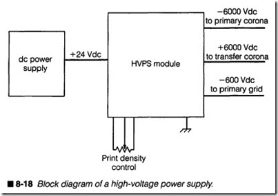
The high-voltage power supply is a vital element of EP printers. High voltage is necessary to operate the primary and transfer coronas, as well as the development unit (where toner is trans ferred to the drum). Older EP printers using discrete corona wires needed thousands of volts for proper operation, so the “SX-type” engines would receive -6,000 V for the primary corona, -600 V for the development unit, and +6,000 V for the transfer corona from the high-voltage power supply (HVPS). Newer EP engines fitted with charge rollers require a bit less voltage, and the correspond ing HVPS will supply -1,000 V for the primary charge roller, -400 V for the development unit, and +1,000 V for the transfer roller. It is important to note that an HVPS uses a +24-V output from the de power supply rather than a connection to raw ac, so if the de power supply quits, so does the high-voltage unit. You can see a simple “black box” representation of the HVPS in figure 8-18.
Troubleshooting the HVPS
The HVPS presents a technician with several important problems that just can’t be ignored. First, it is impossible to measure the output(s) of a high-voltage supply with conventional test instru ments such as multimeters or oscilloscopes. Most conventional in struments do not accept more than 1,000 V, so higher voltages can easily damage the instruments. Most test leads only insulate to 600 V, so you stand an excellent chance of being electrocuted right through the test leads anyway. Ultimately, you will need special ized test equipment and test leads to check an HVPS. The other
nesses and place the old HVPS aside. When you install the new HVPS and attach all of the wiring harnesses (be careful to install all connectors properly and completely), you must be certain to install all ground straps and mounting screws securely. Failure to secure the high-voltage power supply to the chassis could result in a shock hazard, or unstable HVPS operation.
Symptoms
Identifying a failed HVPS is not always such a simple task, espe cially when you cannot measure its outputs. But once you realize that its outputs drive the primary charging area, the development unit, and the transfer area, you can easily understand that the HVPS plays a key role in the image formation process. A low or ab sent -6,000 (or -1,000) V will disable the primary charging mech anism (corona or roller). The net result would be no conditioning charge on the drum, and all pages would be black. A low or absent +6,000 (or + 1,000) V will disable the transfer charging mechanism (corona or roller). No transfer means that no toner would be drawn to the page, so the pages would be white. Of course, the loss of supplemental voltages (i.e., -600 or -400 V) would adversely af fect the primary grid (for corona assemblies) and the develop ment unit, which would also whiten any latent images.
Remember that you should suspect the HVPS only when indicated by symptoms in the print, so refer to Chapter 11 for image forma tion problems. As you review those symptoms, you will see when it is advisable to replace the HVPS.
